8.10.00 J-TRACE ARM Segger Microcontroller Systems, 8.10.00 J-TRACE ARM Datasheet - Page 120
8.10.00 J-TRACE ARM
Manufacturer Part Number
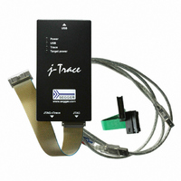
8.10.00 J-TRACE ARM
Description
JTAG EMULATOR ARM7/ARM9 ETM
Manufacturer
Segger Microcontroller Systems
Type
Emulatorr
Specifications of 8.10.00 J-TRACE ARM
Contents
Emulation Module
For Use With/related Products
ARM7, ARM9
Lead Free Status / RoHS Status
Lead free / RoHS Compliant
Other names
899-1006


120
5.8.2
5.8.2.1 Type 0: Normal
5.8.2.2 Type 1: Core
5.8.2.3 Type 2: ResetPin
5.8.2.4 Type 3: Connect under Reset
5.8.2.5 Type 4: Reset core & peripherals, halt after bootloader
J-Link / J-Trace (UM08001)
J-Link supports different specific reset strategies for the Cortex-M cores. All of the
following reset strategies are available in JTAG and in SWD mode. All of them halt the
CPU after the reset.
This is the default strategy. It works well for most Cortex-M devices. J-Link tries to
reset both, core and peripherals by setting the SYSRESETREQ & VECTRESET bits in
the AIRCR. The VC_CORERESET bit is used to halt the CPU before it executes a single
instruction.
On devices that are known to have a bootloader, this bootloader is started after the
core & peripherals have been reset and stopped before trying to start the application
program, thus ensuring that the bootloader (which may perform important initialisa-
tions) has a chance to do so.
This type of RESET can fail:
One reason is that the CPU is in power down state. In this case, the reset pin is used
to reset the device. If this fails as well, then Connect-under-Reset is executed.
Other reasons why the initial reset may not work are typically shortcomings in the
silicon (sometimes only in Beta silicon). Some of these reasons are:
•
•
Only the core is reset via the VECTRESET bit. The peripherals are not affected. After
setting the VECTRESET bit, J-Link waits for the S_RESET_ST bit in the Debug Halting
Control and Status Register (DHCSR) to first become high and then low afterwards.
The CPU does not start execution of the program because J-Link sets the
VC_CORERESET bit before reset, which causes the CPU to halt before execution of
the first instruction.
J-Link pulls its RESET pin low to reset the core and the peripherals. This normally
causes the CPU RESET pin of the target device to go low as well, resulting in a reset
of both CPU and peripherals. This reset strategy will fail if the RESET pin of the target
device is not pulled low. The CPU does not start execution of the program because J-
Link sets the VC_CORERESET bit before reset, which causes the CPU to halt before
execution of the first instruction.
J-Link connects to the target while keeping Reset active (reset is pulled low and
remains low while connecting to the target). This is the recommended reset strategy
for STM32 devices. This reset strategy has been designed for the case that communi-
cation with the core is not possible in normal mode so the VC_CORERESET bit can not
be set in order to guarantee that the core is halted immediately after reset.
Same as type 0, but bootloader is always executed. This reset strategy has been
designed for MCUs/CPUs which have a bootloader located in ROM which needs to run
at first, after reset (since it might initialize some target settings to their reset state).
When using this reset strategy, J-Link will let the bootloader run after reset and halts
the target immediately after the bootloader and before the target application is
started. This is the recommended reset strategy for LPC11xx and LPC13xx devices
where a bootloader should execute after reset to put the chip into the "real" reset
state.
Watchdog continues to run when CPU is halted
SYSRESETREQ also reset debug unit
Strategies for Cortex-M devices
CHAPTER 5
© 2004-2011 SEGGER Microcontroller GmbH & Co. KG
Working with J-Link and J-Trace
Related parts for 8.10.00 J-TRACE ARM
Image
Part Number
Description
Manufacturer
Datasheet
Request
R

Part Number:
Description:
CONNECTOR JTAG-ARM ISOLATION
Manufacturer:
Segger Microcontroller Systems
Datasheet:

Part Number:
Description:
ADAPTER ARM TARGET 14PIN RIBBON
Manufacturer:
Segger Microcontroller Systems
Datasheet:

Part Number:
Description:
JTAG EMULATOR FOR ARM CORES
Manufacturer:
Segger Microcontroller Systems
Datasheet:

Part Number:
Description:
JTAG EMULATOR FOR ARM CORES
Manufacturer:
Segger Microcontroller Systems
Datasheet:

Part Number:
Description:
PROGRAMMING TOOL FOR MCU
Manufacturer:
Segger Microcontroller Systems
Datasheet:

Part Number:
Description:
PROGRAMMING TOOL FOR ST7 MCU
Manufacturer:
Segger Microcontroller Systems
Datasheet:

Part Number:
Description:
PROGRAMMING TOOL FOR STM8
Manufacturer:
Segger Microcontroller Systems
Datasheet:

Part Number:
Description:
PROGRAMMER JTAG FOR ARM CORES
Manufacturer:
Segger Microcontroller Systems
Datasheet:

Part Number:
Description:
JTAG EMULATOR USB ETHERNET ARM
Manufacturer:
Segger Microcontroller Systems
Datasheet:

Part Number:
Description:
EMULATOR JTAG/SWD CORTEX M3
Manufacturer:
Segger Microcontroller Systems
Datasheet: