8.10.00 J-TRACE ARM Segger Microcontroller Systems, 8.10.00 J-TRACE ARM Datasheet - Page 149
8.10.00 J-TRACE ARM
Manufacturer Part Number
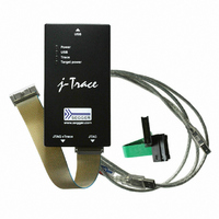
8.10.00 J-TRACE ARM
Description
JTAG EMULATOR ARM7/ARM9 ETM
Manufacturer
Segger Microcontroller Systems
Type
Emulatorr
Specifications of 8.10.00 J-TRACE ARM
Contents
Emulation Module
For Use With/related Products
ARM7, ARM9
Lead Free Status / RoHS Status
Lead free / RoHS Compliant
Other names
899-1006


6.4.3
6.4.4
J-Link / J-Trace (UM08001)
the J-Link status window. When the debug session is running you can modify the set-
tings regarding J-Link ARM FlashDL and FlashBPs, in the Settings tab and save
them in the settings file.
The configuration for the J-Link GDB Server is done by the .gdbinit file. The follow-
ing commands has to be added to the .gdbinit file to enable download into internal
flash memory and flash breakpoints:
monitor flash device <DeviceID>
monitor flash download = 1
monitor flash breakpoints = 1
<DeviceID> is the name of the device for which download into internal flash memory
shall be enabled. For a list of supported, please refer to Supported devices on
page 145. For more information about these three commands please refer to
UM08005, J-Link GDB Server User Guide chapter Supported remote commands.
The configuration for J-Link RDI is done via the J-Link RDI configuration dialog. For
more information about the J-Link RDI configuration dialog please refer to the J-Link
RDI User Guide, chapter Configuration dialog. If you use the J-Link ARM FlashDL
and/or FlashBP feature with RDI disable them in the J-Link status window or leave
the default settings.
J-Link GDB Server
J-Link RDI
© 2004-2011 SEGGER Microcontroller GmbH & Co. KG
149
Related parts for 8.10.00 J-TRACE ARM
Image
Part Number
Description
Manufacturer
Datasheet
Request
R

Part Number:
Description:
CONNECTOR JTAG-ARM ISOLATION
Manufacturer:
Segger Microcontroller Systems
Datasheet:

Part Number:
Description:
ADAPTER ARM TARGET 14PIN RIBBON
Manufacturer:
Segger Microcontroller Systems
Datasheet:

Part Number:
Description:
JTAG EMULATOR FOR ARM CORES
Manufacturer:
Segger Microcontroller Systems
Datasheet:

Part Number:
Description:
JTAG EMULATOR FOR ARM CORES
Manufacturer:
Segger Microcontroller Systems
Datasheet:

Part Number:
Description:
PROGRAMMING TOOL FOR MCU
Manufacturer:
Segger Microcontroller Systems
Datasheet:

Part Number:
Description:
PROGRAMMING TOOL FOR ST7 MCU
Manufacturer:
Segger Microcontroller Systems
Datasheet:

Part Number:
Description:
PROGRAMMING TOOL FOR STM8
Manufacturer:
Segger Microcontroller Systems
Datasheet:

Part Number:
Description:
PROGRAMMER JTAG FOR ARM CORES
Manufacturer:
Segger Microcontroller Systems
Datasheet:

Part Number:
Description:
JTAG EMULATOR USB ETHERNET ARM
Manufacturer:
Segger Microcontroller Systems
Datasheet:

Part Number:
Description:
EMULATOR JTAG/SWD CORTEX M3
Manufacturer:
Segger Microcontroller Systems
Datasheet: