8.10.00 J-TRACE ARM Segger Microcontroller Systems, 8.10.00 J-TRACE ARM Datasheet - Page 209
8.10.00 J-TRACE ARM
Manufacturer Part Number
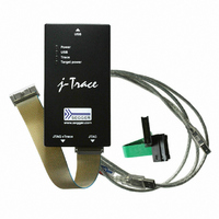
8.10.00 J-TRACE ARM
Description
JTAG EMULATOR ARM7/ARM9 ETM
Manufacturer
Segger Microcontroller Systems
Type
Emulatorr
Specifications of 8.10.00 J-TRACE ARM
Contents
Emulation Module
For Use With/related Products
ARM7, ARM9
Lead Free Status / RoHS Status
Lead free / RoHS Compliant
Other names
899-1006


11.3 Signal analysis
11.3.1 Start sequence
11.3.2 Troubleshooting
J-Link / J-Trace (UM08001)
The following screenshots show the data flow of the startup and ID communication
between J-Link / J-Trace and the target device.
This is the signal sequence output by J-Link / J-Trace at start of JLink.exe . It should
be used as reference when tracing potential J-Link / J-Trace related hardware prob-
lems.
The sequence consists of the following sections:
•
•
•
•
•
•
•
J-Link / J-Trace checks the output of the device (output on TDO) for the signature to
measure the IR length. For ARM7 / ARM9 chips, the IR length is 4, which means TDO
shifts out the data shifted in on TDI with 4 clock cycles delay. If you compare the
screenshot with your own measurements, the signals of TCK, TMS, TDI, and TDO
should be identical.
Note that the TDO signal is undefined for the first 10 clocks, since the output is usu-
ally tristated and the signal level depends on external components connected to TDO,
such as pull-up or pull-down.
Zoom-in
The next screenshot shows the first 6 clock cycles of the screenshot above. For the
first 5 clock cycles, TMS is high (Resulting in a TAP reset). TMS changes to low with
the falling edge of TCK. At this time the TDI signal is low. Your signals should be
identical. Signal rise and fall times should be shorter than 100ns.
If your measurements of TCK, TMS and TDI (the signals output by J-Link / J-Trace)
differ from the results shown, disconnect your target hardware and test the output of
TCK, TMS and TDI without a connection to a target, just supplying voltage to J-
Link’s/J-Trace’s JTAG connector: VCC at pin 1; GND at pin 4.
5 clocks: TDI low, TMS high. Brings TAP controller into RESET state
1 clock: TDI low, TMS low: Brings TAP controller into IDLE state
2 clocks: TDI low, TMS high: Brings TAP controller into IR-SCAN state
2 clocks: TDI low, TMS low: Brings TAP controller into SHIFT-IR state
32 clocks: TMS low, TDI: 0x05253000 (lsb first): J-Link Signature as IR data
240 clocks: TMS low, last clock high, TDI high: Bypass command
1 clock: TDI low, TMS high: Brings TAP controller into UPDATE-IR state.
© 2004-2011 SEGGER Microcontroller GmbH & Co. KG
209
Related parts for 8.10.00 J-TRACE ARM
Image
Part Number
Description
Manufacturer
Datasheet
Request
R

Part Number:
Description:
CONNECTOR JTAG-ARM ISOLATION
Manufacturer:
Segger Microcontroller Systems
Datasheet:

Part Number:
Description:
ADAPTER ARM TARGET 14PIN RIBBON
Manufacturer:
Segger Microcontroller Systems
Datasheet:

Part Number:
Description:
JTAG EMULATOR FOR ARM CORES
Manufacturer:
Segger Microcontroller Systems
Datasheet:

Part Number:
Description:
JTAG EMULATOR FOR ARM CORES
Manufacturer:
Segger Microcontroller Systems
Datasheet:

Part Number:
Description:
PROGRAMMING TOOL FOR MCU
Manufacturer:
Segger Microcontroller Systems
Datasheet:

Part Number:
Description:
PROGRAMMING TOOL FOR ST7 MCU
Manufacturer:
Segger Microcontroller Systems
Datasheet:

Part Number:
Description:
PROGRAMMING TOOL FOR STM8
Manufacturer:
Segger Microcontroller Systems
Datasheet:

Part Number:
Description:
PROGRAMMER JTAG FOR ARM CORES
Manufacturer:
Segger Microcontroller Systems
Datasheet:

Part Number:
Description:
JTAG EMULATOR USB ETHERNET ARM
Manufacturer:
Segger Microcontroller Systems
Datasheet:

Part Number:
Description:
EMULATOR JTAG/SWD CORTEX M3
Manufacturer:
Segger Microcontroller Systems
Datasheet: