8.10.00 J-TRACE ARM Segger Microcontroller Systems, 8.10.00 J-TRACE ARM Datasheet - Page 188
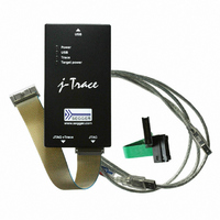
8.10.00 J-TRACE ARM
Manufacturer Part Number
8.10.00 J-TRACE ARM
Description
JTAG EMULATOR ARM7/ARM9 ETM
Manufacturer
Segger Microcontroller Systems
Type
Emulatorr
Specifications of 8.10.00 J-TRACE ARM
Contents
Emulation Module
For Use With/related Products
ARM7, ARM9
Lead Free Status / RoHS Status
Lead free / RoHS Compliant
Other names
899-1006


188
9.1
9.1.1
9.1.2
9.1.3
J-Link / J-Trace (UM08001)
JTAG is the acronym for Joint Test Action Group. In the scope of this document,
"the JTAG standard" means compliance with IEEE Standard 1149.1-2001.
JTAG defines a TAP (Test access port). The TAP is a general-purpose port that can
provide access to many test support functions built into a component. It is composed
as a minimum of the three input connections (TDI, TCK, TMS) and one output con-
nection (TDO). An optional fourth input connection (nTRST) provides for asynchro-
nous initialization of the test logic.
Table 9.1: Test access port
JTAG requires at least two data registers to be present: the bypass and the bound-
ary-scan register. Other registers are allowed but are not obligatory.
Bypass data register
A single-bit register that passes information from TDI to TDO.
Boundary-scan data register
A test data register which allows the testing of board interconnections, access to
input and output of components when testing their system logic and so on.
The instruction register holds the current instruction and its content is used by the
TAP controller to decide which test to perform or which data register to access. It
consist of at least two shift-register cells.
TCK
TDI
TMS
TDO
nTRST
JTAG
PIN
Test access port (TAP)
Data registers
Instruction register
Input
Input
Input
Output
Input
(optional)
Type
The test clock input (TCK) provides the clock for the test
logic.
Serial test instructions and data are received by the test
logic at test data input (TDI).
The signal received at test mode select (TMS) is
decoded by the TAP controller to control test operations.
Test data output (TDO) is the serial output for test
instructions and data from the test logic.
The optional test reset (nTRST) input provides for asyn-
chronous initialization of the TAP controller.
CHAPTER 9
© 2004-2011 SEGGER Microcontroller GmbH & Co. KG
Explanation
Background information
Related parts for 8.10.00 J-TRACE ARM
Image
Part Number
Description
Manufacturer
Datasheet
Request
R

Part Number:
Description:
CONNECTOR JTAG-ARM ISOLATION
Manufacturer:
Segger Microcontroller Systems
Datasheet:

Part Number:
Description:
ADAPTER ARM TARGET 14PIN RIBBON
Manufacturer:
Segger Microcontroller Systems
Datasheet:

Part Number:
Description:
JTAG EMULATOR FOR ARM CORES
Manufacturer:
Segger Microcontroller Systems
Datasheet:

Part Number:
Description:
JTAG EMULATOR FOR ARM CORES
Manufacturer:
Segger Microcontroller Systems
Datasheet:

Part Number:
Description:
PROGRAMMING TOOL FOR MCU
Manufacturer:
Segger Microcontroller Systems
Datasheet:

Part Number:
Description:
PROGRAMMING TOOL FOR ST7 MCU
Manufacturer:
Segger Microcontroller Systems
Datasheet:

Part Number:
Description:
PROGRAMMING TOOL FOR STM8
Manufacturer:
Segger Microcontroller Systems
Datasheet:

Part Number:
Description:
PROGRAMMER JTAG FOR ARM CORES
Manufacturer:
Segger Microcontroller Systems
Datasheet:

Part Number:
Description:
JTAG EMULATOR USB ETHERNET ARM
Manufacturer:
Segger Microcontroller Systems
Datasheet:

Part Number:
Description:
EMULATOR JTAG/SWD CORTEX M3
Manufacturer:
Segger Microcontroller Systems
Datasheet: