8.10.00 J-TRACE ARM Segger Microcontroller Systems, 8.10.00 J-TRACE ARM Datasheet - Page 173
8.10.00 J-TRACE ARM
Manufacturer Part Number
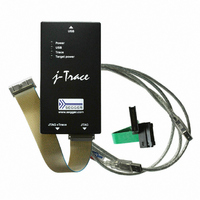
8.10.00 J-TRACE ARM
Description
JTAG EMULATOR ARM7/ARM9 ETM
Manufacturer
Segger Microcontroller Systems
Type
Emulatorr
Specifications of 8.10.00 J-TRACE ARM
Contents
Emulation Module
For Use With/related Products
ARM7, ARM9
Lead Free Status / RoHS Status
Lead free / RoHS Compliant
Other names
899-1006


8.1.1.1 Target board design
8.1.1.2 Pull-up/pull-down resistors
J-Link / J-Trace (UM08001)
** Optional to supply the target board from J-Link.
* NTRST and RTCK may not be available on some CPUs.
Pins 4, 6, 8, 10, 12, 14, 16, 18, 20 are GND pins connected to GND in J-Link. They
should also be connected to GND in the target system.
We strongly advise following the recommendations given by the chip manufacturer.
These recommendations are normally in line with the recommendations given in the
table Pinout for JTAG on page 172. In case of doubt you should follow the recommen-
dations given by the semiconductor manufacturer.
You may take any female header following the specifications of DIN 41651.
For example:
Unless otherwise specified by developer’s manual, pull-ups/pull-downs are recom-
mended to be between 2.2 kOhms and 47 kOhms.
Harting
Molex
Tyco Electronics
J-Link
JTAG connector
Typical target connection for JTAG
5V supply
nTRST
RESET
part-no. 09185206803
part-no. 90635-1202
part-no. 2-215882-0
VTref
RTCK
GND
TMS
TDO
TCK
TDI
3*
5
7
9
11*
13
15
20
19**
1
© 2004-2011 SEGGER Microcontroller GmbH & Co. KG
19
11
13
20
15
1
3
5
7
9
nTRST
TDI
TMS
TCK
RTCK
TDO
nRST
Regulator
Voltage
Target board
CPU
GND
VCC
VCC
173
Related parts for 8.10.00 J-TRACE ARM
Image
Part Number
Description
Manufacturer
Datasheet
Request
R

Part Number:
Description:
CONNECTOR JTAG-ARM ISOLATION
Manufacturer:
Segger Microcontroller Systems
Datasheet:

Part Number:
Description:
ADAPTER ARM TARGET 14PIN RIBBON
Manufacturer:
Segger Microcontroller Systems
Datasheet:

Part Number:
Description:
JTAG EMULATOR FOR ARM CORES
Manufacturer:
Segger Microcontroller Systems
Datasheet:

Part Number:
Description:
JTAG EMULATOR FOR ARM CORES
Manufacturer:
Segger Microcontroller Systems
Datasheet:

Part Number:
Description:
PROGRAMMING TOOL FOR MCU
Manufacturer:
Segger Microcontroller Systems
Datasheet:

Part Number:
Description:
PROGRAMMING TOOL FOR ST7 MCU
Manufacturer:
Segger Microcontroller Systems
Datasheet:

Part Number:
Description:
PROGRAMMING TOOL FOR STM8
Manufacturer:
Segger Microcontroller Systems
Datasheet:

Part Number:
Description:
PROGRAMMER JTAG FOR ARM CORES
Manufacturer:
Segger Microcontroller Systems
Datasheet:

Part Number:
Description:
JTAG EMULATOR USB ETHERNET ARM
Manufacturer:
Segger Microcontroller Systems
Datasheet:

Part Number:
Description:
EMULATOR JTAG/SWD CORTEX M3
Manufacturer:
Segger Microcontroller Systems
Datasheet: