8.07.00 JTAG ISOLATOR Segger Microcontroller Systems, 8.07.00 JTAG ISOLATOR Datasheet
8.07.00 JTAG ISOLATOR
Specifications of 8.07.00 JTAG ISOLATOR


Related parts for 8.07.00 JTAG ISOLATOR


8.07.00 JTAG ISOLATOR Summary of contents
Page 1
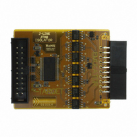
Introduction The J-Link JTAG Isolator can be connected between J-Link ARM and any ARM- board that uses the standard 20-pin JTAG-ARM connector to provide electrical isolation. This is essential when the development tools are not connected to the same ground ...
Page 2
Connectors and indicators The Isolator uses high speed optocouplers that allow a very low propagation time between input and output. It comes with the following connectors and indicators: • 20-pin female EMULATOR connector which can be plugged directly into J- ...
Page 3
Connecting the Isolator to Target and Emulator Figure 3. Connecting the Isolator to Target and Emulator VCC VCC 1 2 nTRST GND 3 4 TDI GND 5 6 TMS GND 7 8 TCK GND 9 10 RTCK GND 11 12 ...
Page 4
Disclaimer Specifications written in this document are believed to be accurate, but are not guaranteed to be entirely free of error. The information in this manual is subject to change for functional or performance improvements without notice. Please make sure ...