8.10.00 J-TRACE ARM Segger Microcontroller Systems, 8.10.00 J-TRACE ARM Datasheet - Page 183
8.10.00 J-TRACE ARM
Manufacturer Part Number
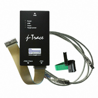
8.10.00 J-TRACE ARM
Description
JTAG EMULATOR ARM7/ARM9 ETM
Manufacturer
Segger Microcontroller Systems
Type
Emulatorr
Specifications of 8.10.00 J-TRACE ARM
Contents
Emulation Module
For Use With/related Products
ARM7, ARM9
Lead Free Status / RoHS Status
Lead free / RoHS Compliant
Other names
899-1006


8.3.1
J-Link / J-Trace (UM08001)
Table 8.8: 19-pin JTAG/SWD and Trace pinout
Pins 3, 5, 15, 17, 19 are GND pins connected to GND in J-Trace CM3. They should
also be connected to GND in the target system.
Pins 11 and 13 of the connector can be used to supply power to the target hardware.
Supply voltage is 5V, max. current is 300mA. The output current is monitored and
protected against overload and short-circuit.
Power can be controlled via the J-Link commander. The following commands are
available to control power:
Table 8.9: Command List
16
18
20
power on
power off
power on perm
power off perm
PIN
Target power supply
TRACE-
DATA[1]
TRACE-
DATA[2]
TRACE-
DATA[3]
SIGNAL
Command
Input
Input
Input
TYPE
Input Trace data pin 0.
Input Trace data pin 0.
Input Trace data pin 0.
Switch target power on
Switch target power off
Set target power supply default to "on"
Set target power supply default to "off"
© 2004-2011 SEGGER Microcontroller GmbH & Co. KG
Explanation
Description
183
Related parts for 8.10.00 J-TRACE ARM
Image
Part Number
Description
Manufacturer
Datasheet
Request
R

Part Number:
Description:
CONNECTOR JTAG-ARM ISOLATION
Manufacturer:
Segger Microcontroller Systems
Datasheet:

Part Number:
Description:
ADAPTER ARM TARGET 14PIN RIBBON
Manufacturer:
Segger Microcontroller Systems
Datasheet:

Part Number:
Description:
JTAG EMULATOR FOR ARM CORES
Manufacturer:
Segger Microcontroller Systems
Datasheet:

Part Number:
Description:
JTAG EMULATOR FOR ARM CORES
Manufacturer:
Segger Microcontroller Systems
Datasheet:

Part Number:
Description:
PROGRAMMING TOOL FOR MCU
Manufacturer:
Segger Microcontroller Systems
Datasheet:

Part Number:
Description:
PROGRAMMING TOOL FOR ST7 MCU
Manufacturer:
Segger Microcontroller Systems
Datasheet:

Part Number:
Description:
PROGRAMMING TOOL FOR STM8
Manufacturer:
Segger Microcontroller Systems
Datasheet:

Part Number:
Description:
PROGRAMMER JTAG FOR ARM CORES
Manufacturer:
Segger Microcontroller Systems
Datasheet:

Part Number:
Description:
JTAG EMULATOR USB ETHERNET ARM
Manufacturer:
Segger Microcontroller Systems
Datasheet:

Part Number:
Description:
EMULATOR JTAG/SWD CORTEX M3
Manufacturer:
Segger Microcontroller Systems
Datasheet: