8.10.00 J-TRACE ARM Segger Microcontroller Systems, 8.10.00 J-TRACE ARM Datasheet - Page 202
8.10.00 J-TRACE ARM
Manufacturer Part Number
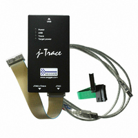
8.10.00 J-TRACE ARM
Description
JTAG EMULATOR ARM7/ARM9 ETM
Manufacturer
Segger Microcontroller Systems
Type
Emulatorr
Specifications of 8.10.00 J-TRACE ARM
Contents
Emulation Module
For Use With/related Products
ARM7, ARM9
Lead Free Status / RoHS Status
Lead free / RoHS Compliant
Other names
899-1006


202
10.1 Overview of high-speed board design
10.1.1 Avoiding stubs
10.1.2 Minimizing Signal Skew (Balancing PCB Track Lengths)
10.1.3 Minimizing Crosstalk
10.1.4 Using impedance matching and termination
J-Link / J-Trace (UM08001)
Failure to observe high-speed design rules when designing a target system contain-
ing an ARM Embedded Trace Macrocell (ETM) trace port can result in incorrect data
being captured by J-Trace.You must give serious consideration to high-speed signals
when designing the target system.
The signals coming from an ARM ETM trace port can have very fast rise and fall
times, even at relatively low frequencies.
Note:
PIPESTAT[0:2], TRACESYNC), but special care must be taken with TRACECLK.
Stubs are short pieces of track that tee off from the main track carrying the signal to,
for example, a test point or a connection to an intermediate device. Stubs cause
impedance discontinuities that affect signal quality and must be avoided.
Special care must therefore be taken when ETM signals are multiplexed with other
pin functions and where the PCB is designed to support both functions with differing
tracking requirements.
You must attempt to match the lengths of the PCB tracks carrying all of TRACECLK,
PIPESTAT, TRACESYNC, and TRACEPKT from the ASIC to the mictor connector to
within approximately 0.5 inches (12.5mm) of each other. Any greater differences
directly impact the setup and hold time requirements.
Normal high-speed design rules must be observed. For example, do not run dynamic
signals parallel to each other for any significant distance, keep them spaced well
apart, and use a ground plane and so forth. Particular attention must be paid to the
TRACECLK signal. If in any doubt, place grounds or static signals between the
TRACECLK and any other dynamic signals.
Termination is almost certainly necessary, but there are some circumstances where it
is not required. The decision is related to track length between the ASIC and the
JTAG+Trace connector, see Terminating the trace signal on page 203 for further ref-
erence.
These principles apply to all of the trace port signals (TRACEPKT[0:15],
CHAPTER 10
© 2004-2011 SEGGER Microcontroller GmbH & Co. KG
Designing the target board for trace
Related parts for 8.10.00 J-TRACE ARM
Image
Part Number
Description
Manufacturer
Datasheet
Request
R

Part Number:
Description:
CONNECTOR JTAG-ARM ISOLATION
Manufacturer:
Segger Microcontroller Systems
Datasheet:

Part Number:
Description:
ADAPTER ARM TARGET 14PIN RIBBON
Manufacturer:
Segger Microcontroller Systems
Datasheet:

Part Number:
Description:
JTAG EMULATOR FOR ARM CORES
Manufacturer:
Segger Microcontroller Systems
Datasheet:

Part Number:
Description:
JTAG EMULATOR FOR ARM CORES
Manufacturer:
Segger Microcontroller Systems
Datasheet:

Part Number:
Description:
PROGRAMMING TOOL FOR MCU
Manufacturer:
Segger Microcontroller Systems
Datasheet:

Part Number:
Description:
PROGRAMMING TOOL FOR ST7 MCU
Manufacturer:
Segger Microcontroller Systems
Datasheet:

Part Number:
Description:
PROGRAMMING TOOL FOR STM8
Manufacturer:
Segger Microcontroller Systems
Datasheet:

Part Number:
Description:
PROGRAMMER JTAG FOR ARM CORES
Manufacturer:
Segger Microcontroller Systems
Datasheet:

Part Number:
Description:
JTAG EMULATOR USB ETHERNET ARM
Manufacturer:
Segger Microcontroller Systems
Datasheet:

Part Number:
Description:
EMULATOR JTAG/SWD CORTEX M3
Manufacturer:
Segger Microcontroller Systems
Datasheet: