8.10.00 J-TRACE ARM Segger Microcontroller Systems, 8.10.00 J-TRACE ARM Datasheet - Page 103
8.10.00 J-TRACE ARM
Manufacturer Part Number
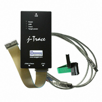
8.10.00 J-TRACE ARM
Description
JTAG EMULATOR ARM7/ARM9 ETM
Manufacturer
Segger Microcontroller Systems
Type
Emulatorr
Specifications of 8.10.00 J-TRACE ARM
Contents
Emulation Module
For Use With/related Products
ARM7, ARM9
Lead Free Status / RoHS Status
Lead free / RoHS Compliant
Other names
899-1006


5.4
5.4.1
5.4.2
5.4.2.1 Max. SWO speeds
5.4.2.2 Configuring SWO speeds
J-Link / J-Trace (UM08001)
The J-Link support ARMs Serial Wire Debug (SWD). SWD replaces the 5-pin JTAG port
with a clock (SWDCLK) and a single bi-directional data pin (SWDIO), providing all the
normal JTAG debug and test functionality. SWDIO and SWCLK are overlaid on the
TMS and TCK pins. In order to communicate with a SWD device, J-Link sends out
data on SWDIO, synchronous to the SWCLK. With every rising edge of SWCLK, one
bit of data is transmitted or received on the SWDIO.
Currently only fixed SWD speed is supported by J-Link. The target is clocked at a
fixed clock speed. The SWD speed which is used for target communication should not
exceed target CPU speed * 10. The maximum SWD speed which is supported by J-
Link depends on the hardware version and model of J-Link. For more information
about the maximum SWD speed for each J-Link / J-Trace model, please refer to J-
Link / J-Trace models on page 22.
Serial Wire Output (SWO) support means support for a single pin output signal from
the core. The Instrumentation Trace Macrocell (ITM) and Serial Wire Output (SWO)
can be used to form a Serial Wire Viewer (SWV). The Serial Wire Viewer provides a
low cost method of obtaining information from inside the MCU.
Usually it should not be necessary to configure the SWO speed because this is usually
done by the debugger.
The supported SWO speeds depend on the connected emulator. They can be retrieved
from the emulator. Currently, the following are supported:
Table 5.6: J-Link supported SWO input speeds
The max. SWO speed in practice is the max. speed which both, target and J-Link can
handle. J-Link can handle the frequencies described in SWO on page 103 whereas the
max. deviation between the target and the J-Link speed is about 3%.
The computation of possible SWO speeds is typically done in the debugger. The SWO
output speed of the CPU is determined by TRACECLKIN, which is normally the same
as the CPU clock.
Example1
Target CPU running at 72 MHz. n is be between 1 and 8192.
Possible SWO output speeds are:
72MHz, 36MHz, 24MHz, ...
J-Link V7: Supported SWO input speeds are: 6MHz / n, n>= 1:
6MHz, 3MHz, 2MHz, 1.5MHz, ...
J-Link V6
J-Link V7/V8
J-Link Pro
SWD interface
SWD speed
SWO
Emulator
6MHz/n, n >= 12
6MHz/n, n >= 1
6MHz/n, n >= 1
Speed formula
© 2004-2011 SEGGER Microcontroller GmbH & Co. KG
500kHz
6MHz
6MHz
Resulting max. speed
103
Related parts for 8.10.00 J-TRACE ARM
Image
Part Number
Description
Manufacturer
Datasheet
Request
R

Part Number:
Description:
CONNECTOR JTAG-ARM ISOLATION
Manufacturer:
Segger Microcontroller Systems
Datasheet:

Part Number:
Description:
ADAPTER ARM TARGET 14PIN RIBBON
Manufacturer:
Segger Microcontroller Systems
Datasheet:

Part Number:
Description:
JTAG EMULATOR FOR ARM CORES
Manufacturer:
Segger Microcontroller Systems
Datasheet:

Part Number:
Description:
JTAG EMULATOR FOR ARM CORES
Manufacturer:
Segger Microcontroller Systems
Datasheet:

Part Number:
Description:
PROGRAMMING TOOL FOR MCU
Manufacturer:
Segger Microcontroller Systems
Datasheet:

Part Number:
Description:
PROGRAMMING TOOL FOR ST7 MCU
Manufacturer:
Segger Microcontroller Systems
Datasheet:

Part Number:
Description:
PROGRAMMING TOOL FOR STM8
Manufacturer:
Segger Microcontroller Systems
Datasheet:

Part Number:
Description:
PROGRAMMER JTAG FOR ARM CORES
Manufacturer:
Segger Microcontroller Systems
Datasheet:

Part Number:
Description:
JTAG EMULATOR USB ETHERNET ARM
Manufacturer:
Segger Microcontroller Systems
Datasheet:

Part Number:
Description:
EMULATOR JTAG/SWD CORTEX M3
Manufacturer:
Segger Microcontroller Systems
Datasheet: