8.10.00 J-TRACE ARM Segger Microcontroller Systems, 8.10.00 J-TRACE ARM Datasheet - Page 203
8.10.00 J-TRACE ARM
Manufacturer Part Number
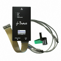
8.10.00 J-TRACE ARM
Description
JTAG EMULATOR ARM7/ARM9 ETM
Manufacturer
Segger Microcontroller Systems
Type
Emulatorr
Specifications of 8.10.00 J-TRACE ARM
Contents
Emulation Module
For Use With/related Products
ARM7, ARM9
Lead Free Status / RoHS Status
Lead free / RoHS Compliant
Other names
899-1006


10.2 Terminating the trace signal
10.2.1 Rules for series terminators
J-Link / J-Trace (UM08001)
To terminate the trace signal, you can choose between three termination options:
•
•
•
Matched impedance
Where available, the best termination scheme is to have the ASIC manufacturer
match the output impedance of the driver to the impedance of the PCB track on your
board. This produces the best possible signal.
Series (source) termination
This method requires a resistor fitted in series with signal. The resistor value plus the
output impedance of the driver must be equal to the PCB track impedance.
DC parallel termination
This requires either a single resistor to ground, or a pull-up/pull-down combination of
resistors (Thevenin termination), fitted at the end of each signal and as close as pos-
sible to the JTAG+Trace connector. If a single resistor is used, its value must be set
equal to the PCB track impedance. If the pull-up/pull-down combination is used, their
resistance values must be selected so that their parallel combination equals the PCB
track impedance.
Caution:
At lower frequencies, parallel termination requires considerably more drive capability
from the ASIC than series termination and so, in practice, DC parallel termination is
rarely used.
Series (source) termination is the most commonly used method. The basic rules are:
1.
2.
3.
Matched impedance
Series (source) termination
DC parallel termination.
The series resistor must be placed as close as possible to the ASIC pin (less than
0.5 inches).
The value of the resistor must equal the impedance of the track minus the output
impedance of the output driver. So for example, a 50 PCB track driven by an out-
put with a 17 impedance, requires a resistor value of 33.
A source terminated signal is only valid at the end of the signal path. At any point
between the source and the end of the track, the signal appears distorted
because of reflections. Any device connected between the source and the end of
the signal path therefore sees the distorted signal and might not operate cor-
rectly. Care must be taken not to connect devices in this way, unless the distor-
tion does not affect device operation.
© 2004-2011 SEGGER Microcontroller GmbH & Co. KG
203
Related parts for 8.10.00 J-TRACE ARM
Image
Part Number
Description
Manufacturer
Datasheet
Request
R

Part Number:
Description:
CONNECTOR JTAG-ARM ISOLATION
Manufacturer:
Segger Microcontroller Systems
Datasheet:

Part Number:
Description:
ADAPTER ARM TARGET 14PIN RIBBON
Manufacturer:
Segger Microcontroller Systems
Datasheet:

Part Number:
Description:
JTAG EMULATOR FOR ARM CORES
Manufacturer:
Segger Microcontroller Systems
Datasheet:

Part Number:
Description:
JTAG EMULATOR FOR ARM CORES
Manufacturer:
Segger Microcontroller Systems
Datasheet:

Part Number:
Description:
PROGRAMMING TOOL FOR MCU
Manufacturer:
Segger Microcontroller Systems
Datasheet:

Part Number:
Description:
PROGRAMMING TOOL FOR ST7 MCU
Manufacturer:
Segger Microcontroller Systems
Datasheet:

Part Number:
Description:
PROGRAMMING TOOL FOR STM8
Manufacturer:
Segger Microcontroller Systems
Datasheet:

Part Number:
Description:
PROGRAMMER JTAG FOR ARM CORES
Manufacturer:
Segger Microcontroller Systems
Datasheet:

Part Number:
Description:
JTAG EMULATOR USB ETHERNET ARM
Manufacturer:
Segger Microcontroller Systems
Datasheet:

Part Number:
Description:
EMULATOR JTAG/SWD CORTEX M3
Manufacturer:
Segger Microcontroller Systems
Datasheet: