8.10.00 J-TRACE ARM Segger Microcontroller Systems, 8.10.00 J-TRACE ARM Datasheet - Page 101
8.10.00 J-TRACE ARM
Manufacturer Part Number
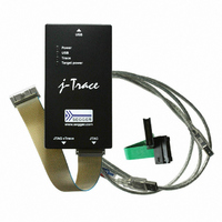
8.10.00 J-TRACE ARM
Description
JTAG EMULATOR ARM7/ARM9 ETM
Manufacturer
Segger Microcontroller Systems
Type
Emulatorr
Specifications of 8.10.00 J-TRACE ARM
Contents
Emulation Module
For Use With/related Products
ARM7, ARM9
Lead Free Status / RoHS Status
Lead free / RoHS Compliant
Other names
899-1006


5.3.3
J-Link / J-Trace (UM08001)
When do I need to configure the scan chain?
If only one device is connected to the scan chain, the default configuration can be
used. In other cases, J-Link / J-Trace may succeed in automatically recognizing the
devices on the scan chain, but whether this is possible depends on the devices
present on the scan chain.
How do I configure the scan chain?
2 values need to be known:
•
•
The position can usually be seen in the schematic; the IR len can be found in the
manual supplied by the manufacturers of the others devices.
ARM7/ARM9 have an IR len of four.
Sample configurations
The diagram below shows a scan chain configuration sample with 2 devices con-
nected to the JTAG port.
Examples
The following table shows a few sample configurations with 1,2 and 3 devices in dif-
ferent configurations.
Table 5.5: Example scan chain configurations
Chip(IR len)
Device 0
Xilinx(8)
Xilinx(8)
ARM(4)
ARM(4)
The position of the target device in the scan chain
The total number of bits in the instruction registers of the devices before the tar-
get device (IR len).
Determining values for scan chain configuration
Chip(IR len)
TDI
Device 1
Xilinx(8)
Xilinx(8)
ARM(4)
-
Device 1
TDI
Chip(IR len)
Device 2
ARM(4)
TDO
-
-
-
JTAG
Position
© 2004-2011 SEGGER Microcontroller GmbH & Co. KG
0
0
1
2
TDI
Device 0
TDO
IR len
16
0
0
8
TDO
101
Related parts for 8.10.00 J-TRACE ARM
Image
Part Number
Description
Manufacturer
Datasheet
Request
R

Part Number:
Description:
CONNECTOR JTAG-ARM ISOLATION
Manufacturer:
Segger Microcontroller Systems
Datasheet:

Part Number:
Description:
ADAPTER ARM TARGET 14PIN RIBBON
Manufacturer:
Segger Microcontroller Systems
Datasheet:

Part Number:
Description:
JTAG EMULATOR FOR ARM CORES
Manufacturer:
Segger Microcontroller Systems
Datasheet:

Part Number:
Description:
JTAG EMULATOR FOR ARM CORES
Manufacturer:
Segger Microcontroller Systems
Datasheet:

Part Number:
Description:
PROGRAMMING TOOL FOR MCU
Manufacturer:
Segger Microcontroller Systems
Datasheet:

Part Number:
Description:
PROGRAMMING TOOL FOR ST7 MCU
Manufacturer:
Segger Microcontroller Systems
Datasheet:

Part Number:
Description:
PROGRAMMING TOOL FOR STM8
Manufacturer:
Segger Microcontroller Systems
Datasheet:

Part Number:
Description:
PROGRAMMER JTAG FOR ARM CORES
Manufacturer:
Segger Microcontroller Systems
Datasheet:

Part Number:
Description:
JTAG EMULATOR USB ETHERNET ARM
Manufacturer:
Segger Microcontroller Systems
Datasheet:

Part Number:
Description:
EMULATOR JTAG/SWD CORTEX M3
Manufacturer:
Segger Microcontroller Systems
Datasheet: