5.07.01 FLASHER ARM Segger Microcontroller Systems, 5.07.01 FLASHER ARM Datasheet
5.07.01 FLASHER ARM
Specifications of 5.07.01 FLASHER ARM


Related parts for 5.07.01 FLASHER ARM


5.07.01 FLASHER ARM Summary of contents
Page 1
Flasher ARM User guide of the stand-alone JTAG programmer for ARM Cores Manual Rev. 18 Date: August 6, 2009 Document: UM08007 A product of SEGGER Microcontroller GmbH & Co. KG www.segger.com ...
Page 2
Disclaimer Specifications written in this document are believed to be accurate, but are not guar- anteed to be entirely free of error. The information in this manual is subject to change for functional or performance improvements without notice. Please ...
Page 3
Revision Date 14 090508 13 090506 12 090122 11 090114 10 081211 9 081113 8 081105 7 081031 6 081030 5 080929 4 080926 3 080912 2 080827 1 080820 0 071204 Flasher ARM (UM08007) By Explanation Chapter "Remote control" ...
Page 4
Flasher ARM (UM08007) © 2004-2009 SEGGER Microcontroller GmbH & Co. KG ...
Page 5
About this document This document describes the Flasher ARM. It provides an overview over the major features of the Flasher ARM, gives you some background information about JTAG, ARM general and describes Flasher ARM related software packages available from Segger. ...
Page 6
Our most popular products are emWin, a universal graphic software package for embed- ded applications, and embOS, a small ...
Page 7
Table of Contents 1 Introduction ......................................................................................................................9 1.1 Flasher ARM overview .............................................................................. 10 1.1.1 Features of Flasher ARM ........................................................................... 10 1.1.2 Working environment ............................................................................... 10 1.2 Specifications.......................................................................................... 11 1.2.1 Specifications for Flasher ARM ................................................................... 11 1.2.2 Flasher ARM Download speed .................................................................... ...
Page 8
Available options for flash programming ..................................................... 50 7 Support and FAQs .........................................................................................................51 7.1 Contacting support .................................................................................. 52 7.2 Frequently Asked Questions...................................................................... 53 8 Glossary.........................................................................................................................55 9 Literature and references...............................................................................................59 Flasher ARM (UM08007) © 2004-2009 SEGGER Microcontroller GmbH & Co. ...
Page 9
Chapter 1 Introduction This chapter gives a short overview about the Flasher ARM. Flasher ARM (UM08007) © 2004-2009 SEGGER Microcontroller GmbH & Co ...
Page 10
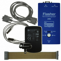
Flasher ARM overview Flasher ARM is a programming tool for microcontrollers with on-chip or external Flash memory and ARM core. Flasher ARM is designed for programming flash targets with the J-Flash software or stand-alone. In addition to that ...
Page 11
Specifications 1.2.1 Specifications for Flasher ARM Power Supply USB Host Interface RS232 Host Interface Target Interface Max. JTAG Transfer Rate Supported Target Voltage Target supply voltage Target supply current Operating Temperature Storage Temperature Relative Humidity (non-condensing) Size (without cables) ...
Page 12
Flasher ARM (UM08007) CHAPTER 1 © 2004-2009 SEGGER Microcontroller GmbH & Co. KG Introduction ...
Page 13
Chapter 2 Working with Flasher ARM This chapter describes functionality and how to use Flasher ARM. Flasher ARM (UM08007) © 2004-2009 SEGGER Microcontroller GmbH & Co ...
Page 14
Operating modes Flasher ARM is able to boot in 3 different modes: • J-Link mode • Stand-alone mode • MSD (Mass storage device) mode If Flasher ARM can enumerate on the USB port, Flasher ARM boots in "J-Link ...
Page 15
User Guide. The J-Link related software and documentation package contains the J- Flash software. When J-Flash is started, open an appropriate J-Flash project file and an appropriate data file for the target you want to program with Flasher ARM. Flasher ...
Page 16
Now, choose File->Download to emulator from the menu in order to download the target configuration as well as the data file to the Flasher ARM. Flasher ARM (UM08007) CHAPTER 2 © 2004-2009 SEGGER Microcontroller GmbH & Co. KG Working ...
Page 17
After the download, you should see in the J-Flash Log window that the Flasher.cfg and the Flasher.dat files have been successfully downloaded. From now on, Flasher ARM can be used in "stand-alone mode" for stand-alone pro- gramming. 2.1.2 Stand-alone mode ...
Page 18
Status of LED GREEN, slow blinking (1 kHz) GREEN RED Table 2.1: Flasher ARM LEDs 2.1.3 MSD mode When pressing the Start/Stop button of Flasher ARM while connecting it to the PC, Flasher ARM will boot in the "MSD ...
Page 19
Multiple File Support It is also possible to have multiple data files and config files on Flasher ARM, to make Flasher ARM more easy to use in production environment. To choose the correct con- figuration file and data file ...
Page 20
Target interfaces Since Flasher ARM is compatible to J-Link it also supports the same target interfaces. Currently the following target interfaces are supported: • JTAG • SWD For more information about the target interfaces itself and the maximum ...
Page 21
Supported microcontrollers The following table lists all the devices which are currently supported by Flasher ARM. Manufacturer Analog Devices Analog Devices Analog Devices Analog Devices Analog Devices Analog Devices Analog Devices Analog Devices Analog Devices Analog Devices Analog Devices ...
Page 22
Manufacturer Freescale Freescale Luminary Luminary Luminary Luminary Luminary Luminary Luminary Luminary Luminary Luminary Luminary Luminary Luminary Luminary Luminary Luminary Luminary Luminary Luminary Luminary Luminary Luminary Luminary Luminary Luminary Luminary Luminary Luminary Luminary Luminary Luminary Luminary Luminary Luminary Luminary Luminary ...
Page 23
Manufacturer Luminary Luminary Luminary Luminary NXP NXP NXP NXP NXP NXP NXP NXP NXP NXP NXP NXP NXP NXP NXP NXP NXP NXP NXP NXP NXP NXP NXP NXP NXP NXP NXP NXP NXP NXP NXP NXP NXP NXP NXP ...
Page 24
Manufacturer NXP NXP NXP NXP NXP NXP NXP ...
Page 25
Manufacturer ...
Page 26
Manufacturer Toshiba Table 2.2: Supported microcontrollers Flasher ARM (UM08007) CHAPTER 2 Devices STR912FAW44 STR912FAW46 STR912FAW47 ...
Page 27
Support of external flashes Flasher ARM supports the programming of CFI compliant, external NOR flashes. For a list of all supported flash devices, please refer to the J-Flash User Guide (UM08003), chapter Supported Flash Devices. Flasher ARM (UM08007) © ...
Page 28
Supported ARM Cores Flasher ARM has been tested with the following cores, but should work with any ARM7/9, Cortex-M0/M1/M3 core. If you experience problems with a particular core, do not hesitate to contact Segger. • ARM7TDMI (Rev 1) ...
Page 29
Chapter 3 Remote control This chapter describes how to control Flasher ARM via the 9-pin serial interface con- nector. Flasher ARM (UM08007) © 2004-2009 SEGGER Microcontroller GmbH & Co ...
Page 30
Overview There are 3 ways to control Flasher ARM operation: • Manual: Programming operation starts when pressing the button. The LEDs serve as visible indication. • Via Handshake lines: 3 lines on the serial interface are used. 1 ...
Page 31
Handshake control Flasher ARM can be remote controlled by automated testers without the need of a connection to PC and Flasher ARM’s PC program. Therefore Flasher ARM is equipped with additional hardware control functions, which are connected to the ...
Page 32
ASCII command interface 3.3.1 Introduction Once set up using J-Flash, Flasher ARM can be driven by any application or just a simple terminal using ASCII commands. Every known command is acknowledged by Flasher and then executed. After com- ...
Page 33
NOINFO This command may be used instead of #AUTO status messages from Flasher should be sent during execution. The NOINFO extension is also available for all other commands. The command ends with #OK or #ERRxxx #ERASE This ...
Page 34
This command can be sent in order to change the baudrate of the UART used for the ASCII command interface communication. <Baudrate> is expected in decimal format. If this command succeeds, Flasher responds with: #ACK #OK Otherwise it ...
Page 35
Note: If deletion of the file fails for example if the file does not exist, Flasher will respond with the following sequence: #ACK #ERR255:Failed to delete file #FWRITE <Offset>,<NumBytes>:<Data> The #FWRITE command is used to write ...
Page 36
If the #FSIZE command succeeds, Flasher will respond with a #OK:<Size> reply mes- sage. For more information about the Flasher reply messages, please refer to Reply from Flasher ARM on page 36. Note: In order to use the #FREAD ...
Page 37
Message #STATUS:ERASING #STATUS:PROGRAMMING #STATUS:VERIFYING Table 3.2: List of status messages that are currently defined Flasher ARM (UM08007) Description Flasher is erasing the flash of the target device. Flasher is programming the flash of the target device. Flasher verifies the programmed ...
Page 38
If any command other than #STATUS or #RESULT was terminated with an error, Flasher cancels the command and replies with an error message instead of #OK mes- sage. Some error codes may be followed by colon and an ...
Page 39
Chapter 4 Performance The following chapter lists programming performance of common flash devices and microcontrollers. Flasher ARM (UM08007) © 2004-2009 SEGGER Microcontroller GmbH & Co ...
Page 40
Performance of MCUs with internal flash memory The following table lists program and erase performance values for different control- lers. Microcontroller Atmel AT91SAM7S64 Atmel AT91SAM7S256 NXP LPC1768 Interface: 4MHz SWD CPU speed: 80 MHz NXP LPC2148 NXP LPC2138 ...
Page 41
Chapter 5 Hardware This chapter gives an overview about Flasher ARM specific hardware details, such as the pinouts and available adapters. Flasher ARM (UM08007) © 2004-2009 SEGGER Microcontroller GmbH & Co ...
Page 42
JTAG Connector Flasher ARM has a JTAG connector compatible with ARM’s Multi-ICE. The JTAG connector way Insulation Displacement Connector (IDC) keyed box header (2.54mm male) that mates with IDC sockets mounted on a ribbon cable. ...
Page 43
Target board design for JTAG We strongly advise following the recommendations given by the chip manufacturer. These recommendations are normally in line with the recommendations given in the table Pinout on page 42. In case of doubt you should ...
Page 44
Using the JTAG connector with SWD The J-Link and J-Trace JTAG is also compatible to ARM’s Serial Wire Debug (SWD). 5.2.1 Pin Out The following table lists the J-Link / J-Trace SWD pinout. PIN SIGNAL TYPE 1 VTref ...
Page 45
RESET, nTRST The TAP controller and ICE logic is reset independently from the ARM core with nTRST (DBGnTRST on synthesizable cores). For the ARM core to operate correctly essential that both signals are asserted after power-up. The ...
Page 46
Adapters 5.4.1 J-Link JTAG Isolator The J-Link JTAG Isolator can be connected between J-Link ARM and any ARMboard that uses the standard 20-pin JTAG-ARM connector to provide electrical isolation. This is essential when the development tools are not ...
Page 47
How to determine the hardware version To determine the hardware version of your Flasher ARM, the first step should be to look at the label at the bottom side of the unit. Flasher ARMs have the hardware ver- sion ...
Page 48
Flasher ARM (UM08007) CHAPTER 5 © 2004-2009 SEGGER Microcontroller GmbH & Co. KG Hardware ...
Page 49
Chapter 6 Background information This chapter provides background information about flash programming in general. It also provides information about how to replace the firmware of Flasher ARM manu- ally. Flasher ARM (UM08007) © 2004-2009 SEGGER Microcontroller GmbH & Co. KG ...
Page 50
Flash programming Flasher ARM comes with a DLL, which allows - amongst other functionalities - reading and writing RAM, CPU registers, starting and stopping the CPU, and setting break- points. 6.1.1 How does flash programming via Flasher ARM ...
Page 51
Chapter 7 Support and FAQs This chapter contains troubleshooting tips together with solutions for common prob- lems which might occur when using Flasher ARM. There are several steps you can take before contacting support. Performing these steps can solve many ...
Page 52
Contacting support Before contacting support, make sure you tried to solve your problem by trying your Flasher ARM with another PC and if possible with another target system to see if it works there. If the device functions ...
Page 53
Frequently Asked Questions Maximum JTAG speed Q: What is the maximum JTAG speed supported by Flasher ARM? A: Flasher ARM’s maximum supported JTAG speed is 12MHz. Maximum download speed Q: What is the maximum download speed? A: The maximum ...
Page 54
Flasher ARM (UM08007) CHAPTER 7 © 2004-2009 SEGGER Microcontroller GmbH & Co. KG Support and FAQs ...
Page 55
Chapter 8 Glossary This chapter describes important terms used throughout this manual. Flasher ARM (UM08007) © 2004-2009 SEGGER Microcontroller GmbH & Co ...
Page 56
Adaptive clocking A technique in which a clock signal is sent out by Flasher ARM. Flasher ARM waits for the returned clock before generating the next clock pulse. The technique allows the Flasher ARM interface unit to adapt to ...
Page 57
Memory coherency A memory is coherent if the value read by a data read or instruction fetch is the value that was most recently written to that location. Obtaining memory coherency is difficult when there are multiple possible physical locations ...
Page 58
TDI The electronic signal input to a TAP controller from the data source (upstream). Usu- ally, this is seen connecting the J-Link / J-Trace Interface Unit to the first TAP control- ler. TDO The electronic signal output from a ...
Page 59
Chapter 9 Literature and references This chapter lists documents, which we think may be useful to gain a deeper under- standing of technical details. Flasher ARM (UM08007) © 2004-2009 SEGGER Microcontroller GmbH & Co ...
Page 60
Reference [J-Link] J-Link / J-Trace User Guide [J-Flash] J-Flash User Guide Table 9.1: Literature and References Flasher ARM (UM08007) CHAPTER 9 Title This document describes J-Link and J-Trace publicly available from SEGGER (www.segger.com). This document describes J-Flash. ...
Page 61
A Adaptive clocking .................................56 B Big-endian ..........................................56 C Cache cleaning ....................................56 Coprocessor ........................................56 D Dirty data ...........................................56 E EmbeddedICE .....................................56 H Halfword .............................................56 Host ...................................................56 I ICache ...............................................56 ID .....................................................56 IEEE 1149.1 ........................................56 Image ................................................56 Instruction Register ..............................56 IR ......................................................56 ...
Page 62
Flasher ARM (UM08007) Index © 2004-2009 SEGGER Microcontroller GmbH & Co. KG ...