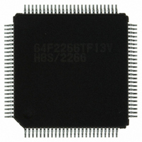
DF2266TF13V Renesas Electronics America, DF2266TF13V Datasheet - Page 602

DF2266TF13V
Manufacturer Part Number
DF2266TF13V
Description
IC H8S/2266 MCU FLASH 100-TQFP
Manufacturer
Renesas Electronics America
Series
H8® H8S/2200r
Datasheet
1.DF2266TF20V.pdf
(712 pages)
Specifications of DF2266TF13V
Core Processor
H8S/2000
Core Size
16-Bit
Speed
13MHz
Connectivity
I²C, SCI, SmartCard
Peripherals
LCD, POR, PWM, WDT
Number Of I /o
67
Program Memory Size
128KB (128K x 8)
Program Memory Type
FLASH
Ram Size
8K x 8
Voltage - Supply (vcc/vdd)
3 V ~ 5.5 V
Data Converters
A/D 10x10b
Oscillator Type
Internal
Operating Temperature
-20°C ~ 75°C
Package / Case
100-TQFP, 100-VQFP
Lead Free Status / RoHS Status
Lead free / RoHS Compliant
Eeprom Size
-
- Current page: 602 of 712
- Download datasheet (5Mb)
Section 21 Clock Pulse Generator
21.8.2
When designing the board, place the crystal resonator and its load capacitors as close as possible
to the XTAL and EXTAL pins. Make wires as short as possible. Other signal lines should be
routed away from the oscillator circuit, as shown in figure 21.11. This is to prevent induction from
interfering with correct oscillation.
21.8.3
When a microcomputer runs, internal power supply potential will fluctuate synchronized with the
system clock. In addition, according to the individual characteristics of crystal resonator, there is
a case where the amplitude of the oscillation waveform will not be grown sufficiently immediately
after oscillation stabilization period, thus the oscillation waveform is easily affected by the
fluctuation of the power supply voltage. In this condition, oscillation waveform will be unstable,
resulting in the system clock instability and malfunction of the microcomputer.
If a malfunction occurs, the setting of the standby timer select 2 to 0 (STS2 to STS0) bits in the
standby control register (SBYCR) must be set so as for the standby time to be longer.
For example, if a malfunction occurs when the standby time is set to 8192 states, the operation
should be confirmed by setting the standby time to 16384 states or longer.
In addition, if a malfunction similar to at state transition occurs at reset, the RES pin hold time
must be set longer.
Rev. 5.00 Sep. 01, 2009 Page 550 of 656
REJ09B0071-0500
Note on Board Design
Note on Using a Crystal Resonator
Figure 21.11 Note on Board Design of Oscillator Circuit
Avoid
C2
C1
Signal A Signal B
XTAL, OSC2
EXTAL, OSC1
This LSI
Related parts for DF2266TF13V
Image
Part Number
Description
Manufacturer
Datasheet
Request
R

Part Number:
Description:
CONN SOCKET 2POS 7.92MM WHITE
Manufacturer:
Hirose Electric Co Ltd
Datasheet:

Part Number:
Description:
CONN SOCKET 4POS 7.92MM WHITE
Manufacturer:
Hirose Electric Co Ltd
Datasheet:

Part Number:
Description:
CONN SOCKET 5POS 7.92MM WHITE
Manufacturer:
Hirose Electric Co Ltd
Datasheet:

Part Number:
Description:
CONN SOCKET 3POS 7.92MM WHITE
Manufacturer:
Hirose Electric Co Ltd
Datasheet:

Part Number:
Description:
CONN SOCKET 5POS 7.92MM WHITE
Manufacturer:
Hirose Electric Co Ltd
Datasheet:

Part Number:
Description:
CONN SOCKET 2POS 7.92MM WHITE
Manufacturer:
Hirose Electric Co Ltd
Datasheet:

Part Number:
Description:
CONN SOCKET 3POS 7.92MM WHITE
Manufacturer:
Hirose Electric Co Ltd
Datasheet:

Part Number:
Description:
CONN SOCKET 4POS 7.92MM WHITE
Manufacturer:
Hirose Electric Co Ltd
Datasheet:

Part Number:
Description:
CONN HEADER 2POS 7.92MM R/A TIN
Manufacturer:
Hirose Electric Co Ltd
Datasheet:

Part Number:
Description:
CONN HEADER 4POS 7.92MM R/A TIN
Manufacturer:
Hirose Electric Co Ltd
Datasheet:

Part Number:
Description:
KIT STARTER FOR M16C/29
Manufacturer:
Renesas Electronics America
Datasheet:

Part Number:
Description:
KIT STARTER FOR R8C/2D
Manufacturer:
Renesas Electronics America
Datasheet:

Part Number:
Description:
R0K33062P STARTER KIT
Manufacturer:
Renesas Electronics America
Datasheet:

Part Number:
Description:
KIT STARTER FOR R8C/23 E8A
Manufacturer:
Renesas Electronics America
Datasheet:

Part Number:
Description:
KIT STARTER FOR R8C/25
Manufacturer:
Renesas Electronics America
Datasheet:


