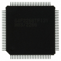
DF2266TF13V Renesas Electronics America, DF2266TF13V Datasheet - Page 587

DF2266TF13V
Manufacturer Part Number
DF2266TF13V
Description
IC H8S/2266 MCU FLASH 100-TQFP
Manufacturer
Renesas Electronics America
Series
H8® H8S/2200r
Datasheet
1.DF2266TF20V.pdf
(712 pages)
Specifications of DF2266TF13V
Core Processor
H8S/2000
Core Size
16-Bit
Speed
13MHz
Connectivity
I²C, SCI, SmartCard
Peripherals
LCD, POR, PWM, WDT
Number Of I /o
67
Program Memory Size
128KB (128K x 8)
Program Memory Type
FLASH
Ram Size
8K x 8
Voltage - Supply (vcc/vdd)
3 V ~ 5.5 V
Data Converters
A/D 10x10b
Oscillator Type
Internal
Operating Temperature
-20°C ~ 75°C
Package / Case
100-TQFP, 100-VQFP
Lead Free Status / RoHS Status
Lead free / RoHS Compliant
Eeprom Size
-
- Current page: 587 of 712
- Download datasheet (5Mb)
Do not touch the socket adapter or chip during programming: Touching either of these can
cause contact faults and write errors.
Reset the flash memory before turning on the power: To reset the flash memory during
oscillation stabilization period, the reset signal must be input for at least 100 µs.
Apply the reset signal while SWE1 is low to reset the flash memory during its operation: The
reset signal is applied at least 100 µs after the SWE1 bit has been cleared.
V
FWE
MD2, MD1 *
RES
SWE1bit
φ
CC
Notes:
Period during which flash memory access is prohibited
(t
Period during which flash memory can be programmed
(Execution of program in flash memory prohibited, and data reads other than verify operations
prohibited)
1.
2.
3.
sswe
1
Except when switching modes, the level of the mode pins (MD2, MD1) must be fixed until
power-off by pulling the pins up or down.
See section 25.2.8, Flash Memory Characteristics.
Mode programming setup time t
: Wait time after setting SWE1 bit) *
Figure 20.13 Power-On/Off Timing (Boot Mode)
t
OSC1
SWE1 set
t
Wait time:
MDS
t
MDS
*
MDS
3
*
3
(min.) = 200ns.
2
t
sswe
Programming/
erasing
possible
Rev. 5.00 Sep. 01, 2009 Page 535 of 656
Wait time:
min 0µs
SWE1 cleared
100µs
min 0µs
REJ09B0071-0500
Section 20 ROM
Related parts for DF2266TF13V
Image
Part Number
Description
Manufacturer
Datasheet
Request
R

Part Number:
Description:
CONN SOCKET 2POS 7.92MM WHITE
Manufacturer:
Hirose Electric Co Ltd
Datasheet:

Part Number:
Description:
CONN SOCKET 4POS 7.92MM WHITE
Manufacturer:
Hirose Electric Co Ltd
Datasheet:

Part Number:
Description:
CONN SOCKET 5POS 7.92MM WHITE
Manufacturer:
Hirose Electric Co Ltd
Datasheet:

Part Number:
Description:
CONN SOCKET 3POS 7.92MM WHITE
Manufacturer:
Hirose Electric Co Ltd
Datasheet:

Part Number:
Description:
CONN SOCKET 5POS 7.92MM WHITE
Manufacturer:
Hirose Electric Co Ltd
Datasheet:

Part Number:
Description:
CONN SOCKET 2POS 7.92MM WHITE
Manufacturer:
Hirose Electric Co Ltd
Datasheet:

Part Number:
Description:
CONN SOCKET 3POS 7.92MM WHITE
Manufacturer:
Hirose Electric Co Ltd
Datasheet:

Part Number:
Description:
CONN SOCKET 4POS 7.92MM WHITE
Manufacturer:
Hirose Electric Co Ltd
Datasheet:

Part Number:
Description:
CONN HEADER 2POS 7.92MM R/A TIN
Manufacturer:
Hirose Electric Co Ltd
Datasheet:

Part Number:
Description:
CONN HEADER 4POS 7.92MM R/A TIN
Manufacturer:
Hirose Electric Co Ltd
Datasheet:

Part Number:
Description:
KIT STARTER FOR M16C/29
Manufacturer:
Renesas Electronics America
Datasheet:

Part Number:
Description:
KIT STARTER FOR R8C/2D
Manufacturer:
Renesas Electronics America
Datasheet:

Part Number:
Description:
R0K33062P STARTER KIT
Manufacturer:
Renesas Electronics America
Datasheet:

Part Number:
Description:
KIT STARTER FOR R8C/23 E8A
Manufacturer:
Renesas Electronics America
Datasheet:

Part Number:
Description:
KIT STARTER FOR R8C/25
Manufacturer:
Renesas Electronics America
Datasheet:


