EVB9311 SMSC, EVB9311 Datasheet - Page 99
EVB9311
Manufacturer Part Number
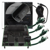
EVB9311
Description
EVALUATION BOARD LAN9311-NU
Manufacturer
SMSC
Series
0133r
Datasheet
1.LAN9311-NU.pdf
(460 pages)
Specifications of EVB9311
Main Purpose
Interface, Ethernet
Embedded
No
Utilized Ic / Part
LAN9311
Primary Attributes
2 Ports, 100BASE-TX/10BASE-T, Managed
Secondary Attributes
2 PHYs with HP Auto-MDIX, Auto- Flow Control, 32-bit CRC, MDI/MDI-X
Lead Free Status / RoHS Status
Lead free / RoHS Compliant
Other names
638-1076


Two Port 10/100 Managed Ethernet Switch with 16-Bit Non-PCI CPU Interface
Datasheet
Chapter 8 Host Bus Interface (HBI)
SMSC LAN9311/LAN9311i
8.1
8.2
8.3
The Host Bus Interface (HBI) module provides a high-speed asynchronous SRAM-like slave interface
that facilitates communication between the LAN9311/LAN9311i and a host system. The HBI allows
access to the System CSRs and handles byte swapping based on the dynamic endianess select. The
HBI interfaces to the switch fabric via the Host MAC, which contains the TX/RX Data and Status FIFOs,
Host MAC registers and power management features. Refer to
for detailed information on the Host MAC.
The following is an overview of the functions provided by the HBI:
Asynchronous 16-bit Host Bus Interface: The HBI provides an asynchronous SRAM-like Host Bus
Interface that is compatible with most CPUs.
System CSR’s: The HBI allows for configuration and monitoring of the various LAN9311/LAN9311i
functions through the System Control and Status Registers (CSRs). These registers are accessible to
the host via the Host Bus Interface and allow direct (and indirect) access to all the LAN9311/LAN9311i
functions. For a full list of all System CSR’s and their descriptions, refer to
Control and Status
Interrupt support: The HBI supports a variety of interrupt sources. Individual interrupts can be
monitored and enabled/disabled via registers within the System CSRs for output on the IRQ pin. For
more information on interrupts, refer to
For a list of all HBI related pins, refer to
Configuration.
The host memory map has two unique modes: normal operation mode, and direct FIFO access mode.
During normal operation, the base address decode map is as described in
allowing access to the full range of System Management CSRs and the TX/RX Data and Status FIFOs.
This is the default mode of operation. The second mode of operation is the direct FIFO access mode.
In direct FIFO access mode, all host write operations are to the TX Data FIFO and all host read
operations are from the RX Data FIFO. Refer to
page 168
The host data bus is 16-bits wide. Two writes or reads must be performed back-to-back, as detailed
below, for proper communication.
Note: When accessing the device, the pair of cycles must be atomic. The first host bus cycle is
Functional Overview
Host Memory Mapping
Host Data Bus
Host data bus endianess control: The HBI supports dynamic selection of big and little endian
host byte ordering based on the END_SEL input pin. This highly flexible interface provides mixed
endian access for registers and memory.
Direct FIFO access modes: When the FIFO_SEL input pin is high during host access, all host
write operations are to the TX data FIFO and all host read operations are from the RX data FIFOs.
This feature facilitates operation with host DMA controllers that do not support FIFO operations.
performed to the low/high WORD and the second host bus cycle is performed to the high/low
WORD forming a 32-bit transaction with no cycles to the LAN9311/LAN9311i in between. With
the exception of A[1], all address and control signals must be the same for both 16-bit cycles
of a 32-bit transaction.
for additional information.
Registers".
DATASHEET
Chapter 5, "System Interrupts," on page
99
Table 3.4 on page 30
Section 14.1.3, "Direct FIFO Access Mode," on
Chapter 9, "Host MAC," on page 113
in
Chapter 3, Pin Description and
Figure 14.1 on page
Section 14.2, "System
49.
Revision 1.7 (06-29-10)
167,
Related parts for EVB9311
Image
Part Number
Description
Manufacturer
Datasheet
Request
R


Part Number:
Description:
FAST ETHERNET PHYSICAL LAYER DEVICE
Manufacturer:
SMSC Corporation
Datasheet:
Part Number:
Description:
357-036-542-201 CARDEDGE 36POS DL .156 BLK LOPRO
Manufacturer:
SMSC Corporation
Datasheet:
Part Number:
Description:
357-036-542-201 CARDEDGE 36POS DL .156 BLK LOPRO
Manufacturer:
SMSC Corporation
Datasheet:
Part Number:
Description:
357-036-542-201 CARDEDGE 36POS DL .156 BLK LOPRO
Manufacturer:
SMSC Corporation
Datasheet:
Part Number:
Description:
4-PORT USB2.0 HUB CONTROLLER
Manufacturer:
SMSC Corporation
Datasheet:
Part Number:
Description:
Manufacturer:
SMSC Corporation
Datasheet:
Part Number:
Description:
Manufacturer:
SMSC Corporation
Datasheet:
Part Number:
Description:
FDC37C672ENHANCED SUPER I/O CONTROLLER WITH FAST IR
Manufacturer:
SMSC Corporation
Datasheet:
Part Number:
Description:
COM90C66LJPARCNET Controller/Transceiver with AT Interface and On-Chip RAM
Manufacturer:
SMSC Corporation
Datasheet:
Part Number:
Description:
Manufacturer:
SMSC Corporation
Datasheet:
Part Number:
Description:
Manufacturer:
SMSC Corporation
Datasheet:
Part Number:
Description:
Manufacturer:
SMSC Corporation
Datasheet:
Part Number:
Description:
Manufacturer:
SMSC Corporation
Datasheet: