EVB9311 SMSC, EVB9311 Datasheet - Page 164
EVB9311
Manufacturer Part Number
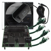
EVB9311
Description
EVALUATION BOARD LAN9311-NU
Manufacturer
SMSC
Series
0133r
Datasheet
1.LAN9311-NU.pdf
(460 pages)
Specifications of EVB9311
Main Purpose
Interface, Ethernet
Embedded
No
Utilized Ic / Part
LAN9311
Primary Attributes
2 Ports, 100BASE-TX/10BASE-T, Managed
Secondary Attributes
2 PHYs with HP Auto-MDIX, Auto- Flow Control, 32-bit CRC, MDI/MDI-X
Lead Free Status / RoHS Status
Lead free / RoHS Compliant
Other names
638-1076


Revision 1.7 (06-29-10)
13.2.1
13.2.1.1
13.2.1.2
13.2.2
13.2.2.1
GPIO IEEE 1588 Timestamping
Two of the GPIO pins, GPIO[9:8], have the option to be used for IEEE 1588 time stamp functions. This
allows a time stamp capture to be triggered when the GPIO is configured as an input, or output a signal
from the GPIO based on an IEEE 1588 clock target compare event when configured as an output.
Refer to
on the IEEE 1588 time stamping functions of the LAN9311/LAN9311i.
IEEE 1588 GPIO Inputs
When the GPIO[9:8] pins are configured as inputs, an active edge will capture the IEEE 1588 clock
into the high and low 1588 capture registers (1588_CLOCK_HI_CAPTURE_GPIO_x, and
1588_CLOCK_LO_CAPTURE_GPIO_x where “x” represents the number of the respective 1588
enabled GPIO) and set the corresponding interrupt flags GPIO[9:8]_INT and 1588_GPIO[9:8]_INT in
the
Interrupt Status and Enable Register (1588_INT_STS_EN)
be configured to clear the Clock Target interrupt (1588_TIMER_INT) in the
E n a b l e
GPIO_1588_TIMER_INT_CLEAR_EN[9:8] bit in the
(GPIO_CFG). GPIO inputs must be active for greater than 40nS to be recognized as capture or
interrupt clear events.
IEEE 1588 GPIO Outputs
The GPIO[9:8] pins can be configured as IEEE 1588 enabled outputs by setting the corresponding
1588_GPIO_OE[9:8] bits in the
override the GPDIR[9:8] bits of the
and allow for GPIO output generation based on the IEEE 1588 clock target compare event. Clock
target compare events occur when the value loaded into the
( 1 5 8 8 _ C L O C K _ TA R G E T _ H I )
(1588_CLOCK_TARGET_LO)
DWORD Register (1588_CLOCK_HI)
Upon detection of a clock target compare event, GPIO[9:8] can be configured to output a 100nS pulse,
toggle its output, or reflect the 1588_TIMER_INT bit in the
(1588_INT_STS_EN)
Configuration Register
1588 GPIO output is active high or active low, is controlled via the GPIO_EVENT_POL_9 and
GPIO_EVENT_POL_8 bits of the
Note: The 1588_GPIO_OE[9:8] bits do not override the GPIO buffer type bits GPIOBUF[9:8] in the
GPIO Interrupts
Each GPIO of the LAN9311/LAN9311i provides the ability to trigger a unique GPIO interrupt in the
General Purpose I/O Interrupt Status and Enable Register
GPIO_INT[11:0] bits of this register provides the current status of the corresponding interrupt, and each
interrupt is enabled by setting the corresponding GPIO_INT_EN[11:0] bit. The GPIO/LED Controller
aggregates the enabled interrupt values into an internal signal which is sent to the System Interrupt
Controller and is reflected via the
information on the LAN9311/LAN9311i interrupts, refer to
GPIO Interrupt Polarity
The interrupt polarity can be set for each individual GPIO via the GPIO_INT_POL[11:0] bits in the
General Purpose I/O Configuration Register
pin will set the corresponding interrupt bit in the
Register
corresponding interrupt bit. Because GPIO[9:8] have added IEEE 1588 functionality, the
General Purpose I/O Interrupt Status and Enable Register (GPIO_INT_STS_EN)
General Purpose I/O Configuration Register
Chapter 11, "IEEE 1588 Hardware Time Stamp Unit," on page 155
(GPIO_INT_STS_EN). When cleared, a low logic level on the GPIO pin will set the
R e g i s t e r
(1588_CONFIG). The clock event polarity, which determines whether the IEEE
by enabling the GPIO_EVENT_9 or GPIO_EVENT_8 bits of the
( 1 5 8 8 _ I N T _ S T S _ E N )
matches the current IEEE 1588 clock value in the
General Purpose I/O Configuration Register
General Purpose I/O Configuration Register
DATASHEET
General Purpose I/O Data & Direction Register (GPIO_DATA_DIR)
Interrupt Status Register (INT_STS)
a n d
and
164
1588 Clock Low-DWORD Register
Two Port 10/100 Managed Ethernet Switch with 16-Bit Non-PCI CPU Interface
1 5 8 8
(GPIO_CFG). When set, a high logic level on the GPIO
General Purpose I/O Interrupt Status and Enable
(GPIO_CFG).
C l o c k
General Purpose I/O Configuration Register
b y
Chapter 5, "System Interrupts," on page
respectively. The GPIO[9:8] inputs can also
1588 Interrupt Status and Enable Register
1588 Clock Target High-DWORD Register
Ta r g e t
s e t t i n g
(GPIO_INT_STS_EN). Reading the
L o w - D W O R D
bit 12 (GPIO). For more
1588 Interrupt Status and
t h e
for additional information
(GPIO_CFG). These bits
(1588_CLOCK_LO).
SMSC LAN9311/LAN9311i
(GPIO_CFG).
1588 Clock High-
c o r r e s p o n d i n g
R e g i s t e r
and
Datasheet
1588
1588
49.
Related parts for EVB9311
Image
Part Number
Description
Manufacturer
Datasheet
Request
R


Part Number:
Description:
FAST ETHERNET PHYSICAL LAYER DEVICE
Manufacturer:
SMSC Corporation
Datasheet:
Part Number:
Description:
357-036-542-201 CARDEDGE 36POS DL .156 BLK LOPRO
Manufacturer:
SMSC Corporation
Datasheet:
Part Number:
Description:
357-036-542-201 CARDEDGE 36POS DL .156 BLK LOPRO
Manufacturer:
SMSC Corporation
Datasheet:
Part Number:
Description:
357-036-542-201 CARDEDGE 36POS DL .156 BLK LOPRO
Manufacturer:
SMSC Corporation
Datasheet:
Part Number:
Description:
4-PORT USB2.0 HUB CONTROLLER
Manufacturer:
SMSC Corporation
Datasheet:
Part Number:
Description:
Manufacturer:
SMSC Corporation
Datasheet:
Part Number:
Description:
Manufacturer:
SMSC Corporation
Datasheet:
Part Number:
Description:
FDC37C672ENHANCED SUPER I/O CONTROLLER WITH FAST IR
Manufacturer:
SMSC Corporation
Datasheet:
Part Number:
Description:
COM90C66LJPARCNET Controller/Transceiver with AT Interface and On-Chip RAM
Manufacturer:
SMSC Corporation
Datasheet:
Part Number:
Description:
Manufacturer:
SMSC Corporation
Datasheet:
Part Number:
Description:
Manufacturer:
SMSC Corporation
Datasheet:
Part Number:
Description:
Manufacturer:
SMSC Corporation
Datasheet:
Part Number:
Description:
Manufacturer:
SMSC Corporation
Datasheet: