EVB9311 SMSC, EVB9311 Datasheet - Page 46
EVB9311
Manufacturer Part Number
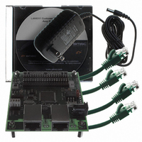
EVB9311
Description
EVALUATION BOARD LAN9311-NU
Manufacturer
SMSC
Series
0133r
Datasheet
1.LAN9311-NU.pdf
(460 pages)
Specifications of EVB9311
Main Purpose
Interface, Ethernet
Embedded
No
Utilized Ic / Part
LAN9311
Primary Attributes
2 Ports, 100BASE-TX/10BASE-T, Managed
Secondary Attributes
2 PHYs with HP Auto-MDIX, Auto- Flow Control, 32-bit CRC, MDI/MDI-X
Lead Free Status / RoHS Status
Lead free / RoHS Compliant
Other names
638-1076


Revision 1.7 (06-29-10)
4.3
eeprom_type_strap
eeprom_size_strap[1:0]
phy_addr_sel_strap
STRAP NAME
The LAN9311/LAN9311i Port 1 and Port 2 PHYs and the Host MAC support several power
management and wakeup features.
The LAN9311/LAN9311i can be programmed to issue an external wake signal (PME) via several
methods, including wake on LAN, wake on link status change (energy detect), and magic packet
wakeup. The PME signal is ideal for triggering system power-up using remote Ethernet wakeup events.
A simplified diagram of the logic that controls the PME and PME_INT signals can be seen in
Figure
The PME module handles the latching of the Port 1 & 2 PHY Energy-Detect Status (ED_STS1 and
ED_STS2) and Wake-On LAN Status (WOL_STS) bits of the
(PMT_CTRL). This module also masks the status bits with the corresponding enable bits (ED_EN1,
ED_EN2, WOL_EN) and combines the results together to generate the PME_INT status bit in the
Interrupt Status Register
conditioned before becoming the PME output pin.
The PME output characteristics can be configured via the PME_TYPE, PME_IND, and PME_POL bits
of the
active high push-pull, or active-low push-pull and configure the output to be continuous, or pulse for
50mS.
Power Management
Power Management Control Register
4.1.
Table 4.3 Hard-Strap Configuration Strap Definitions
EEPROM Type Strap: Configures the EEPROM type.
0 = Microwire Mode
1 = I
EEPROM Size Strap [1:0]: Configures the EEPROM size
range as specified in
EEPROM Controller," on page
PHY Address Select Strap: Configures the default MII
management address values for the PHYs and Virtual PHY
as detailed in
0
1
2
(INT_STS). The PME_INT status bit is then masked with the PME_EN bit and
C Mode
0
1
Section 7.1.1, "PHY Addressing," on page
DATASHEET
1
2
Section 10.2, "I2C/Microwire Master
DESCRIPTION
46
Two Port 10/100 Managed Ethernet Switch with 16-Bit Non-PCI CPU Interface
(PMT_CTRL). These bits allow the PME to be open-drain,
2
3
138.
Power Management Control Register
82.
SMSC LAN9311/LAN9311i
EEPROM_TYPE
EEPROM_SIZE_[1:0]
PHY_ADDR_SEL
PIN
Datasheet
Related parts for EVB9311
Image
Part Number
Description
Manufacturer
Datasheet
Request
R


Part Number:
Description:
FAST ETHERNET PHYSICAL LAYER DEVICE
Manufacturer:
SMSC Corporation
Datasheet:
Part Number:
Description:
357-036-542-201 CARDEDGE 36POS DL .156 BLK LOPRO
Manufacturer:
SMSC Corporation
Datasheet:
Part Number:
Description:
357-036-542-201 CARDEDGE 36POS DL .156 BLK LOPRO
Manufacturer:
SMSC Corporation
Datasheet:
Part Number:
Description:
357-036-542-201 CARDEDGE 36POS DL .156 BLK LOPRO
Manufacturer:
SMSC Corporation
Datasheet:
Part Number:
Description:
4-PORT USB2.0 HUB CONTROLLER
Manufacturer:
SMSC Corporation
Datasheet:
Part Number:
Description:
Manufacturer:
SMSC Corporation
Datasheet:
Part Number:
Description:
Manufacturer:
SMSC Corporation
Datasheet:
Part Number:
Description:
FDC37C672ENHANCED SUPER I/O CONTROLLER WITH FAST IR
Manufacturer:
SMSC Corporation
Datasheet:
Part Number:
Description:
COM90C66LJPARCNET Controller/Transceiver with AT Interface and On-Chip RAM
Manufacturer:
SMSC Corporation
Datasheet:
Part Number:
Description:
Manufacturer:
SMSC Corporation
Datasheet:
Part Number:
Description:
Manufacturer:
SMSC Corporation
Datasheet:
Part Number:
Description:
Manufacturer:
SMSC Corporation
Datasheet:
Part Number:
Description:
Manufacturer:
SMSC Corporation
Datasheet: