EVB9311 SMSC, EVB9311 Datasheet - Page 38
EVB9311
Manufacturer Part Number
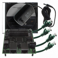
EVB9311
Description
EVALUATION BOARD LAN9311-NU
Manufacturer
SMSC
Series
0133r
Datasheet
1.LAN9311-NU.pdf
(460 pages)
Specifications of EVB9311
Main Purpose
Interface, Ethernet
Embedded
No
Utilized Ic / Part
LAN9311
Primary Attributes
2 Ports, 100BASE-TX/10BASE-T, Managed
Secondary Attributes
2 PHYs with HP Auto-MDIX, Auto- Flow Control, 32-bit CRC, MDI/MDI-X
Lead Free Status / RoHS Status
Lead free / RoHS Compliant
Other names
638-1076


Revision 1.7 (06-29-10)
4.2.1.1
4.2.1.2
4.2.2
4.2.2.1
Power-On Reset (POR)
A power-on reset occurs whenever power is initially applied to the LAN9311/LAN9311i, or if the power
is removed and reapplied to the LAN9311/LAN9311i. This event resets all circuitry within the device.
Configuration straps are latched, and the EEPROM Loader is run as a result of this reset.
A POR reset typically takes approximately 23mS, plus additional time (91uS for I
Microwire) per byte of data loaded from the EEPROM via the EEPROM Loader. A full EEPROM load
(64KB for I
80mS for Microwire EEPROM.
nRST Pin Reset
Driving the nRST input pin low initiates a chip-level reset. This event resets all circuitry within the
device. Use of this reset input is optional, but when used, it must be driven for the period of time
specified in
are latched, and the EEPROM Loader is run as a result of this reset.
A nRST pin reset typically takes approximately 760uS, plus additional time (91uS for I
Microwire) per byte of data loaded from the EEPROM via the EEPROM Loader. A full EEPROM load
(64KB for I
58mS for Microwire EEPROM.
Note: The nRST pin is pulled-high internally. If unused, this signal can be left unconnected. Do not
Please refer to
Multi-Module Resets
Multi-module resets activate multiple internal resets, but do not reset the entire chip. Configuration
straps are not latched upon multi-module resets. A multi-module reset is initiated by assertion of the
following:
Chip-level reset completion/configuration can be determined by polling the READY bit of the
Configuration Register (HW_CFG)
When set, the READY bit indicates that the reset has completed and the device is ready to be
accessed.
With the exception of the
Register
(RESET_CTL), read access to any internal resources is forbidden while the READY bit is cleared.
Writes to any address are invalid until the READY bit is set.
Note: The digital reset and soft reset do not reset register bits designated as NASR.
Note: The LAN9311/LAN9311i must be read at least once after a multi-module reset to ensure that
Digital Reset (DIGITAL_RST)
A digital reset is performed by setting the DIGITAL_RST bit of the
(RESET_CTL). A digital reset will reset all LAN9311/LAN9311i sub-modules except the Ethernet PHYs
(Port 1 PHY, Port 2 PHY, and Virtual PHY). The EEPROM Loader will automatically run following this
reset. Configuration straps are not latched as a result of a digital reset.
A digital reset typically takes approximately 760uS, plus additional time (91uS for I
Microwire) per byte of data loaded from the EEPROM via the EEPROM Loader. A full EEPROM load
Digital Reset (DIGITAL_RST)
Soft Reset (SRST)
rely on internal pull-up resistors to drive signals external to the device.
write operations function properly.
(PMT_CTRL),
2
2
Section 15.5.2, "Reset and Configuration Strap Timing," on page
C, 2KB for Microwire) will complete in approximately 6.0 seconds for I
C, 2KB for Microwire) will complete in approximately 6.0 seconds for I
Section Table 3.7, "Miscellaneous Pins," on page 34
Byte Order Test Register
Hardware Configuration Register
or
DATASHEET
Power Management Control Register (PMT_CTRL)
38
Two Port 10/100 Managed Ethernet Switch with 16-Bit Non-PCI CPU Interface
(BYTE_TEST), and
(HW_CFG),
for a description of the nRST pin.
Power Management Control
Reset Control Register
Reset Control Register
445. Configuration straps
SMSC LAN9311/LAN9311i
2
2
C EEPROM, and
C EEPROM, and
2
2
2
C, 28uS for
until it is set.
C, 28uS for
C, 28uS for
Hardware
Datasheet
Related parts for EVB9311
Image
Part Number
Description
Manufacturer
Datasheet
Request
R


Part Number:
Description:
FAST ETHERNET PHYSICAL LAYER DEVICE
Manufacturer:
SMSC Corporation
Datasheet:
Part Number:
Description:
357-036-542-201 CARDEDGE 36POS DL .156 BLK LOPRO
Manufacturer:
SMSC Corporation
Datasheet:
Part Number:
Description:
357-036-542-201 CARDEDGE 36POS DL .156 BLK LOPRO
Manufacturer:
SMSC Corporation
Datasheet:
Part Number:
Description:
357-036-542-201 CARDEDGE 36POS DL .156 BLK LOPRO
Manufacturer:
SMSC Corporation
Datasheet:
Part Number:
Description:
4-PORT USB2.0 HUB CONTROLLER
Manufacturer:
SMSC Corporation
Datasheet:
Part Number:
Description:
Manufacturer:
SMSC Corporation
Datasheet:
Part Number:
Description:
Manufacturer:
SMSC Corporation
Datasheet:
Part Number:
Description:
FDC37C672ENHANCED SUPER I/O CONTROLLER WITH FAST IR
Manufacturer:
SMSC Corporation
Datasheet:
Part Number:
Description:
COM90C66LJPARCNET Controller/Transceiver with AT Interface and On-Chip RAM
Manufacturer:
SMSC Corporation
Datasheet:
Part Number:
Description:
Manufacturer:
SMSC Corporation
Datasheet:
Part Number:
Description:
Manufacturer:
SMSC Corporation
Datasheet:
Part Number:
Description:
Manufacturer:
SMSC Corporation
Datasheet:
Part Number:
Description:
Manufacturer:
SMSC Corporation
Datasheet: