EVB9311 SMSC, EVB9311 Datasheet - Page 93
EVB9311
Manufacturer Part Number
EVB9311
Description
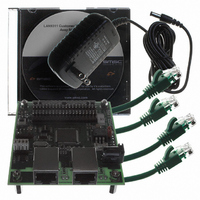
EVALUATION BOARD LAN9311-NU
Manufacturer
SMSC
Series
0133r
Datasheet
1.LAN9311-NU.pdf
(460 pages)
Specifications of EVB9311
Main Purpose
Interface, Ethernet
Embedded
No
Utilized Ic / Part
LAN9311
Primary Attributes
2 Ports, 100BASE-TX/10BASE-T, Managed
Secondary Attributes
2 PHYs with HP Auto-MDIX, Auto- Flow Control, 32-bit CRC, MDI/MDI-X
Lead Free Status / RoHS Status
Lead free / RoHS Compliant
Other names
638-1076


Two Port 10/100 Managed Ethernet Switch with 16-Bit Non-PCI CPU Interface
Datasheet
SMSC LAN9311/LAN9311i
7.2.5.5
7.2.6
7.2.7
Half Vs. Full-Duplex
Half-duplex operation relies on the CSMA/CD (Carrier Sense Multiple Access / Collision Detect)
protocol to handle network traffic and collisions. In this mode, the carrier sense signal, CRS, responds
to both transmit and receive activity. If data is received while the PHY is transmitting, a collision results.
In full-duplex mode, the PHY is able to transmit and receive data simultaneously. In this mode, CRS
responds only to receive activity. The CSMA/CD protocol does not apply and collision detection is
disabled.
HP Auto-MDIX
HP Auto-MDIX facilitates the use of CAT-3 (10 BASE-T) or CAT-5 (100 BASE-T) media UTP
interconnect cable without consideration of interface wiring scheme. If a user plugs in either a direct
connect LAN cable or a cross-over patch cable, as shown in
PHY is capable of configuring the TXPx/TXNx and RXPx/RXNx twisted pair pins for correct transceiver
operation.
The internal logic of the device detects the TX and RX pins of the connecting device. Since the RX
and TX line pairs are interchangeable, special PCB design considerations are needed to accommodate
the symmetrical magnetics and termination of an Auto-MDIX design.
The Auto-MDIX function can be disabled through bit 15 (AMDIXCTRL) of the
Control/Status Indication Register
cleared, Auto-MDIX can be selected via the auto_mdix_strap_x configuration strap. The MDIX can also
be configured manually via the manual_mdix_strap_x if both the AMDIXCTRL bit and the
auto_mdix_strap_x configuration strap are low. Refer to
more information on the configuration straps.
When bit 15 (AMDIXCTRL) of the
(PHY_SPECIAL_CONTROL_STAT_IND_x)
1 3
(PHY_SPECIAL_CONTROL_STAT_IND_x).
MII MAC Interface
The MII MAC Interface is responsible for the transmission and reception of the Ethernet data to and
from the switch fabric MAC. The PHY is connected internally to the switch fabric MAC via standard
MII signals per IEEE 802.3.
Not Used
Not Used
Not Used
Not Used
a n d
RXNx
TXNx
RXPx
TXPx
Figure 7.4 Direct Cable Connection vs. Cross-Over Cable Connection
RJ-45 8-pin straight-through
1 4 o f
1
2
3
4
5
6
7
8
for 10BASE-T/100BASE-TX
Direct Connect Cable
signaling
t h e
P o r t
1
2
3
4
5
6
7
8
TXPx
TXNx
RXPx
Not Used
Not Used
RXNx
Not Used
Not Used
x
(PHY_SPECIAL_CONTROL_STAT_IND_x). When AMDIXCTRL is
DATASHEET
P H Y
Port x PHY Special Control/Status Indication Register
93
is set to 1, the Auto-MDIX capability is determined by bits
Sp e c i a l
Not Used
Not Used
Not Used
Not Used
RXPx
RXNx
TXPx
TXNx
Section 3.2, "Pin Descriptions," on page 28
1
2
3
4
5
6
7
8
C o n t r o l / St a t u s
RJ-45 8-pin cross-over for
10BASE-T/100BASE-TX
Cross-Over Cable
Figure 7.4
signaling
(See
1
2
3
4
5
6
7
8
I n d i c a t i o n
TXPx
TXNx
RXPx
Not Used
Not Used
RXNx
Not Used
Not Used
Note 7.1 on page
Revision 1.7 (06-29-10)
Port x PHY Special
R e g i s t e r
83)
, the
for
Related parts for EVB9311
Image
Part Number
Description
Manufacturer
Datasheet
Request
R


Part Number:
Description:
FAST ETHERNET PHYSICAL LAYER DEVICE
Manufacturer:
SMSC Corporation
Datasheet:
Part Number:
Description:
357-036-542-201 CARDEDGE 36POS DL .156 BLK LOPRO
Manufacturer:
SMSC Corporation
Datasheet:
Part Number:
Description:
357-036-542-201 CARDEDGE 36POS DL .156 BLK LOPRO
Manufacturer:
SMSC Corporation
Datasheet:
Part Number:
Description:
357-036-542-201 CARDEDGE 36POS DL .156 BLK LOPRO
Manufacturer:
SMSC Corporation
Datasheet:
Part Number:
Description:
4-PORT USB2.0 HUB CONTROLLER
Manufacturer:
SMSC Corporation
Datasheet:
Part Number:
Description:
Manufacturer:
SMSC Corporation
Datasheet:
Part Number:
Description:
Manufacturer:
SMSC Corporation
Datasheet:
Part Number:
Description:
FDC37C672ENHANCED SUPER I/O CONTROLLER WITH FAST IR
Manufacturer:
SMSC Corporation
Datasheet:
Part Number:
Description:
COM90C66LJPARCNET Controller/Transceiver with AT Interface and On-Chip RAM
Manufacturer:
SMSC Corporation
Datasheet:
Part Number:
Description:
Manufacturer:
SMSC Corporation
Datasheet:
Part Number:
Description:
Manufacturer:
SMSC Corporation
Datasheet:
Part Number:
Description:
Manufacturer:
SMSC Corporation
Datasheet:
Part Number:
Description:
Manufacturer:
SMSC Corporation
Datasheet: