EVB9311 SMSC, EVB9311 Datasheet - Page 140
EVB9311
Manufacturer Part Number
EVB9311
Description
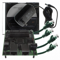
EVALUATION BOARD LAN9311-NU
Manufacturer
SMSC
Series
0133r
Datasheet
1.LAN9311-NU.pdf
(460 pages)
Specifications of EVB9311
Main Purpose
Interface, Ethernet
Embedded
No
Utilized Ic / Part
LAN9311
Primary Attributes
2 Ports, 100BASE-TX/10BASE-T, Managed
Secondary Attributes
2 PHYs with HP Auto-MDIX, Auto- Flow Control, 32-bit CRC, MDI/MDI-X
Lead Free Status / RoHS Status
Lead free / RoHS Compliant
Other names
638-1076


Revision 1.7 (06-29-10)
10.2.2
Figure 10.1
I
The I
transmission and reception, acknowledge generation and reception) for connection to I
and consists of a data wire (EE_SDA) and a serial clock (EE_SCL). The serial clock is driven by the
master, while the data wire is bi-directional. Both signals are open-drain and require external pull-up
resistors.
The serial clock is also used as an input as it can be held low by the slave device in order to wait-
state the data cycle. Once the slave has data available or is ready to receive, it will release the clock.
Assuming the masters clock low time is also expired, the clock will rise and the cycle will continue. In
the event that the slave device holds the clock low for more than 30mS, the current command
sequence is aborted and the EPC_TIMEOUT bit in the
set. Both the clock and data signals have Schmitt trigger inputs and digital input filters. The digital filters
reject pulses that are less than 100nS.
Note: Since the I
Based on the configuration strap eeprom_size_strap, various sized I
varying size ranges are supported by additional bits in the address field (EPC_ADDRESS) of the
EEPROM Command Register
address bits, while the smaller EEPROMs treat the upper address bits as don’t cares. The EEPROM
2
C EEPROM
2
EPC_BUSY = 0
C master implements a low level serial interface (start and stop condition generation, data bit
supported.
illustrates the process required to perform an EEPROM read or write operation.
EEPROM Write
2
C master is designed to access EEPROM only, multi-master arbitration is not
Figure 10.1 EEPROM Access Flow Diagram
E2P_DATA
E2P_CMD
E2P_CMD
Register
Register
Register
Write
Write
Read
Idle
(E2P_CMD). Within each size range, the largest EEPROM uses all the
DATASHEET
140
Two Port 10/100 Managed Ethernet Switch with 16-Bit Non-PCI CPU Interface
EEPROM Command Register (E2P_CMD)
EEPROM Read
E2P_DATA
E2P_CMD
E2P_CMD
Register
Register
Register
Write
Read
Read
Idle
2
C EEPROMs are supported. The
EPC_BUSY = 0
SMSC LAN9311/LAN9311i
2
C EEPROMs,
Datasheet
is
Related parts for EVB9311
Image
Part Number
Description
Manufacturer
Datasheet
Request
R


Part Number:
Description:
FAST ETHERNET PHYSICAL LAYER DEVICE
Manufacturer:
SMSC Corporation
Datasheet:
Part Number:
Description:
357-036-542-201 CARDEDGE 36POS DL .156 BLK LOPRO
Manufacturer:
SMSC Corporation
Datasheet:
Part Number:
Description:
357-036-542-201 CARDEDGE 36POS DL .156 BLK LOPRO
Manufacturer:
SMSC Corporation
Datasheet:
Part Number:
Description:
357-036-542-201 CARDEDGE 36POS DL .156 BLK LOPRO
Manufacturer:
SMSC Corporation
Datasheet:
Part Number:
Description:
4-PORT USB2.0 HUB CONTROLLER
Manufacturer:
SMSC Corporation
Datasheet:
Part Number:
Description:
Manufacturer:
SMSC Corporation
Datasheet:
Part Number:
Description:
Manufacturer:
SMSC Corporation
Datasheet:
Part Number:
Description:
FDC37C672ENHANCED SUPER I/O CONTROLLER WITH FAST IR
Manufacturer:
SMSC Corporation
Datasheet:
Part Number:
Description:
COM90C66LJPARCNET Controller/Transceiver with AT Interface and On-Chip RAM
Manufacturer:
SMSC Corporation
Datasheet:
Part Number:
Description:
Manufacturer:
SMSC Corporation
Datasheet:
Part Number:
Description:
Manufacturer:
SMSC Corporation
Datasheet:
Part Number:
Description:
Manufacturer:
SMSC Corporation
Datasheet:
Part Number:
Description:
Manufacturer:
SMSC Corporation
Datasheet: