EVB9311 SMSC, EVB9311 Datasheet - Page 87
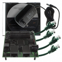
EVB9311
Manufacturer Part Number
EVB9311
Description
EVALUATION BOARD LAN9311-NU
Manufacturer
SMSC
Series
0133r
Datasheet
1.LAN9311-NU.pdf
(460 pages)
Specifications of EVB9311
Main Purpose
Interface, Ethernet
Embedded
No
Utilized Ic / Part
LAN9311
Primary Attributes
2 Ports, 100BASE-TX/10BASE-T, Managed
Secondary Attributes
2 PHYs with HP Auto-MDIX, Auto- Flow Control, 32-bit CRC, MDI/MDI-X
Lead Free Status / RoHS Status
Lead free / RoHS Compliant
Other names
638-1076


Two Port 10/100 Managed Ethernet Switch with 16-Bit Non-PCI CPU Interface
Datasheet
SMSC LAN9311/LAN9311i
7.2.2
7.2.2.1
7.2.2.2
Port x
MAC
Converter
Converter
NRZI
A/D
100BASE-TX Receive
The 100BASE-TX receive data path is shown in
to the PHY. Each major block is explained in the following sections.
A/D Converter
The MLT-3 data from the cable is fed into the PHY on inputs RXPx and RXNx (where “x” is replaced
with “1” for the Port 1 PHY, or “2” for the Port 2 PHY) via a 1:1 ratio transformer. The ADC samples
the incoming differential signal at a rate of 125M samples per second. Using a 64-level quantizer, 6
digital bits are generated to represent each sample. The DSP adjusts the gain of the A/D Converter
(ADC) according to the observed signal levels such that the full dynamic range of the ADC can be
used.
DSP: Equalizer, BLW Correction and Clock/Data Recovery
The 6 bits from the ADC are fed into the DSP block. The equalizer in the DSP section compensates
for phase and amplitude distortion caused by the physical channel (magnetics, connectors, and CAT-
5 cable). The equalizer can restore the signal for any good-quality CAT-5 cable between 1m and 150m.
If the DC content of the signal is such that the low-frequency components fall below the low frequency
pole of the isolation transformer, then the droop characteristics of the transformer will become
significant and Baseline Wander (BLW) on the received signal will result. To prevent corruption of the
received data, the PHY corrects for BLW and can receive the ANSI X3.263-1995 FDDI TP-PMD
defined “killer packet” with no bit errors.
The 100M PLL generates multiple phases of the 125MHz clock. A multiplexer, controlled by the timing
unit of the DSP, selects the optimum phase for sampling the data. This is used as the received
recovered clock. This clock is used to extract the serial data from the received signal.
MII 25MHz by 4 bits
MII Receive Clock
Internal
Internal
MLT-3
NRZI
Magnetics
Converter
Figure 7.3 100BASE-TX Receive Data Path
MII MAC
Interface
MLT-3
100M
PLL
MLT-3
DATASHEET
by 4 bits
25MHz
125 Mbps Serial
MLT-3
6 bit Data
87
RJ45
Figure
Decoder
4B/5B
and BLW Correction
7.3. Shaded blocks are those which are internal
recovery, Equalizer
MLT-3
DSP: Timing
CAT-5
25MHz by
5 bits
Descrambler
Revision 1.7 (06-29-10)
and SIPO
Related parts for EVB9311
Image
Part Number
Description
Manufacturer
Datasheet
Request
R


Part Number:
Description:
FAST ETHERNET PHYSICAL LAYER DEVICE
Manufacturer:
SMSC Corporation
Datasheet:
Part Number:
Description:
357-036-542-201 CARDEDGE 36POS DL .156 BLK LOPRO
Manufacturer:
SMSC Corporation
Datasheet:
Part Number:
Description:
357-036-542-201 CARDEDGE 36POS DL .156 BLK LOPRO
Manufacturer:
SMSC Corporation
Datasheet:
Part Number:
Description:
357-036-542-201 CARDEDGE 36POS DL .156 BLK LOPRO
Manufacturer:
SMSC Corporation
Datasheet:
Part Number:
Description:
4-PORT USB2.0 HUB CONTROLLER
Manufacturer:
SMSC Corporation
Datasheet:
Part Number:
Description:
Manufacturer:
SMSC Corporation
Datasheet:
Part Number:
Description:
Manufacturer:
SMSC Corporation
Datasheet:
Part Number:
Description:
FDC37C672ENHANCED SUPER I/O CONTROLLER WITH FAST IR
Manufacturer:
SMSC Corporation
Datasheet:
Part Number:
Description:
COM90C66LJPARCNET Controller/Transceiver with AT Interface and On-Chip RAM
Manufacturer:
SMSC Corporation
Datasheet:
Part Number:
Description:
Manufacturer:
SMSC Corporation
Datasheet:
Part Number:
Description:
Manufacturer:
SMSC Corporation
Datasheet:
Part Number:
Description:
Manufacturer:
SMSC Corporation
Datasheet:
Part Number:
Description:
Manufacturer:
SMSC Corporation
Datasheet: