EVB9311 SMSC, EVB9311 Datasheet - Page 56
EVB9311
Manufacturer Part Number
EVB9311
Description
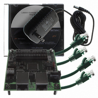
EVALUATION BOARD LAN9311-NU
Manufacturer
SMSC
Series
0133r
Datasheet
1.LAN9311-NU.pdf
(460 pages)
Specifications of EVB9311
Main Purpose
Interface, Ethernet
Embedded
No
Utilized Ic / Part
LAN9311
Primary Attributes
2 Ports, 100BASE-TX/10BASE-T, Managed
Secondary Attributes
2 PHYs with HP Auto-MDIX, Auto- Flow Control, 32-bit CRC, MDI/MDI-X
Lead Free Status / RoHS Status
Lead free / RoHS Compliant
Other names
638-1076


Two Port 10/100 Managed Ethernet Switch with 16-Bit Non-PCI CPU Interface
Datasheet
6.2.1
Switch Fabric CSR Writes
To perform a write to an individual switch fabric register, the desired data must first be written into the
Switch Fabric CSR Interface Data Register
(SWITCH_CSR_DATA). The write cycle is initiated by
p e r f o r m i n g a s i n g l e w r i t e t o t h e
S w i t c h F a b r i c C S R I n t e r f a c e C o m m a n d R e g i s t e r
(SWITCH_CSR_CMD)
with CSR_BUSY (bit 31) set, the CSR_ADDRESS field (bits 15:0) set to the
desired register address, the R_nW (bit 30) cleared, the AUTO_INC and AUTO_DEC fields cleared,
and the desired CSR byte enable bits selected (bits 19:16). The completion of the write cycle is
indicated by the clearing of the CSR_BUSY bit.
A second write method may be used which utilizes the auto increment/decrement function of the
Switch Fabric CSR Interface Command Register (SWITCH_CSR_CMD)
for writing sequential register
addresses. When using this method, the
Switch Fabric CSR Interface Command Register
(SWITCH_CSR_CMD)
must first be written with the auto increment(AUTO_INC) or auto
decrement(AUTO_DEC) bit set, the CSR_ADDRESS field written with the desired register address, the
R_nW bit cleared, and the desired CSR byte enable bits selected (typically all set). The write cycles
are then initiated by writing the desired data into the
Switch Fabric CSR Interface Data Register
(SWITCH_CSR_DATA). The completion of the write cycle is indicated by the clearing of the
CSR_BUSY bit, at which time the address in the
Switch Fabric CSR Interface Command Register
(SWITCH_CSR_CMD)
is incremented or decremented accordingly. The user may then initiate a
subsequent write cycle by writing the desired data into the
Switch Fabric CSR Interface Data Register
(SWITCH_CSR_DATA).
The third write method is to use the direct data range write function. Writes within the
Switch Fabric
CSR Interface Direct Data Register (SWITCH_CSR_DIRECT_DATA)
address range automatically set
the appropriate register address, set all four byte enable bits (CSR_BE[3:0]), clears the R_nW bit, and
s e t s t h e C S R _ B U S Y b i t o f t h e
S w i t c h F a b r i c C S R I n t e r f a c e C o m m a n d R e g i s t e r
(SWITCH_CSR_CMD). The completion of the write cycle is indicated by the clearing of the
CSR_BUSY bit. Since the address range of the switch fabric CSRs exceeds that of the
Switch Fabric
CSR Interface Direct Data Register (SWITCH_CSR_DIRECT_DATA)
address range, a sub-set of the
switch fabric CSRs are mapped to the
Switch Fabric CSR Interface Direct Data Register
(SWITCH_CSR_DIRECT_DATA)
address range as detailed in
Table 14.3, “Switch Fabric CSR to
SWITCH_CSR_DIRECT_DATA Address Range Map,” on page
241.
Figure 6.1
illustrates the process required to perform a switch fabric CSR write. The minimum wait
periods as specified in
Table 8.1, “Read After Write Timing Rules,” on page 103
are required where
noted.
Revision 1.7 (06-29-10)
56
SMSC LAN9311/LAN9311i
DATASHEET
Related parts for EVB9311
Image
Part Number
Description
Manufacturer
Datasheet
Request
R


Part Number:
Description:
FAST ETHERNET PHYSICAL LAYER DEVICE
Manufacturer:
SMSC Corporation
Datasheet:
Part Number:
Description:
357-036-542-201 CARDEDGE 36POS DL .156 BLK LOPRO
Manufacturer:
SMSC Corporation
Datasheet:
Part Number:
Description:
357-036-542-201 CARDEDGE 36POS DL .156 BLK LOPRO
Manufacturer:
SMSC Corporation
Datasheet:
Part Number:
Description:
357-036-542-201 CARDEDGE 36POS DL .156 BLK LOPRO
Manufacturer:
SMSC Corporation
Datasheet:
Part Number:
Description:
4-PORT USB2.0 HUB CONTROLLER
Manufacturer:
SMSC Corporation
Datasheet:
Part Number:
Description:
Manufacturer:
SMSC Corporation
Datasheet:
Part Number:
Description:
Manufacturer:
SMSC Corporation
Datasheet:
Part Number:
Description:
FDC37C672ENHANCED SUPER I/O CONTROLLER WITH FAST IR
Manufacturer:
SMSC Corporation
Datasheet:
Part Number:
Description:
COM90C66LJPARCNET Controller/Transceiver with AT Interface and On-Chip RAM
Manufacturer:
SMSC Corporation
Datasheet:
Part Number:
Description:
Manufacturer:
SMSC Corporation
Datasheet:
Part Number:
Description:
Manufacturer:
SMSC Corporation
Datasheet:
Part Number:
Description:
Manufacturer:
SMSC Corporation
Datasheet:
Part Number:
Description:
Manufacturer:
SMSC Corporation
Datasheet: