EVB9311 SMSC, EVB9311 Datasheet - Page 121
EVB9311
Manufacturer Part Number
EVB9311
Description
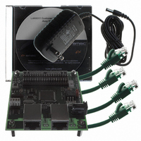
EVALUATION BOARD LAN9311-NU
Manufacturer
SMSC
Series
0133r
Datasheet
1.LAN9311-NU.pdf
(460 pages)
Specifications of EVB9311
Main Purpose
Interface, Ethernet
Embedded
No
Utilized Ic / Part
LAN9311
Primary Attributes
2 Ports, 100BASE-TX/10BASE-T, Managed
Secondary Attributes
2 PHYs with HP Auto-MDIX, Auto- Flow Control, 32-bit CRC, MDI/MDI-X
Lead Free Status / RoHS Status
Lead free / RoHS Compliant
Other names
638-1076


Two Port 10/100 Managed Ethernet Switch with 16-Bit Non-PCI CPU Interface
Datasheet
SMSC LAN9311/LAN9311i
9.7
9.7.1
9.7.2
Note: By convention, the right nibble of the left most byte of the Ethernet address (in this example,
For more information on the EEPROM and EEPROM Loader, refer to
Master EEPROM Controller," on page
The LAN9311/LAN9311i contains four host-accessible FIFOs (TX Status, RX Status, TX Data, and RX
Data) and two internal inaccessible Host MAC TX/RX MIL FIFO’s (TX MIL FIFO, RX MIL FIFO).
TX/RX FIFOs
The TX/RX Data and Status FIFOs store the incoming and outgoing address and data information,
acting as a conduit between the host bus interface (HBI) and the Host MAC. The sizes of these FIFOs
are configurable via the
in
The the RX and TX FIFOs related register definitions can be found in section
MAC &
The TX and RX Data FIFOs have the base address of 00h and 20h respectively. However, each FIFO
is also accessible at seven additional contiguous memory locations, as can be seen in
The Host may access the TX or RX Data FIFOs at any of these alias port locations, as they all function
identically and contain the same data. This alias port addressing is implemented to allow hosts to burst
through sequential addresses.
The TX and RX Status FIFOs can each be read from two register locations; the Status FIFO Port, and
the Status FIFO PEEK. The TX and RX Status FIFO Ports (48h and 40h respectively) will perform a
destructive read, popping the data from the TX or RX Status FIFO. The TX and RX Status FIFO PEEK
register locations (4Ch and 44h respectively) allow a non-destructive read of the top (oldest) location
of the FIFOs.
Proper use of the The TX/RX Data and Status FIFOs, including the correct data formatting is described
in detail in
Operation," on page
MIL FIFOs
The MAC Interface Layer (MIL), within the Host MAC, contains a 2KB transmit and a 128 Byte receive
FIFO which are separate from the TX and RX FIFOs. These MIL FIFOs are not directly accessible
from the HBI. The differentiation between the TX/RX FIFOs and the TX/RX MIL FIFOs is that once the
transmit or receive packets are in the MIL FIFOs, the host no longer can control or access the TX or
RX data. The MIL FIFOs are essentially the working buffers of the Host MAC logic. In the case of
reception, the data must be moved into the RX FIFOs before the host can access the data. For TX
FIFOs
Table
the 2 of the 12h) is the most significant nibble and is transmitted/received first.
FIFO’s".
9.8. Refer to
Section 9.8, "TX Data Path Operation," on page 123
HMAC_ADDRH / SWITCH_MAC_ADDRH
31
31
HMAC_ADDRL / SWITCH_MAC_ADDRL
78h
xx
Figure 9.2 Example EEPROM MAC Address Setup
24
24
133.
Section 9.7.3, "FIFO Memory Allocation Configuration"
23
23
Hardware Configuration Register (HW_CFG)
56h
xx
16
16
15
15
BCh
34h
DATASHEET
8
8
138.
7
7
121
9Ah
12h
0
0
06h
05h
04h
03h
02h
01h
00h
EEPROM
and
BCh
9Ah
A5h
78h
56h
34h
12h
register to the ranges described
Section 10.2, "I2C/Microwire
Section 9.9, "RX Data Path
for additional information.
Section 14.2.2, "Host
Revision 1.7 (06-29-10)
Figure
14.1.
Related parts for EVB9311
Image
Part Number
Description
Manufacturer
Datasheet
Request
R


Part Number:
Description:
FAST ETHERNET PHYSICAL LAYER DEVICE
Manufacturer:
SMSC Corporation
Datasheet:
Part Number:
Description:
357-036-542-201 CARDEDGE 36POS DL .156 BLK LOPRO
Manufacturer:
SMSC Corporation
Datasheet:
Part Number:
Description:
357-036-542-201 CARDEDGE 36POS DL .156 BLK LOPRO
Manufacturer:
SMSC Corporation
Datasheet:
Part Number:
Description:
357-036-542-201 CARDEDGE 36POS DL .156 BLK LOPRO
Manufacturer:
SMSC Corporation
Datasheet:
Part Number:
Description:
4-PORT USB2.0 HUB CONTROLLER
Manufacturer:
SMSC Corporation
Datasheet:
Part Number:
Description:
Manufacturer:
SMSC Corporation
Datasheet:
Part Number:
Description:
Manufacturer:
SMSC Corporation
Datasheet:
Part Number:
Description:
FDC37C672ENHANCED SUPER I/O CONTROLLER WITH FAST IR
Manufacturer:
SMSC Corporation
Datasheet:
Part Number:
Description:
COM90C66LJPARCNET Controller/Transceiver with AT Interface and On-Chip RAM
Manufacturer:
SMSC Corporation
Datasheet:
Part Number:
Description:
Manufacturer:
SMSC Corporation
Datasheet:
Part Number:
Description:
Manufacturer:
SMSC Corporation
Datasheet:
Part Number:
Description:
Manufacturer:
SMSC Corporation
Datasheet:
Part Number:
Description:
Manufacturer:
SMSC Corporation
Datasheet: