EVB9311 SMSC, EVB9311 Datasheet - Page 150
EVB9311
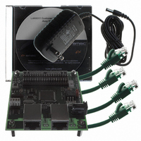
Manufacturer Part Number
EVB9311
Description
EVALUATION BOARD LAN9311-NU
Manufacturer
SMSC
Series
0133r
Datasheet
1.LAN9311-NU.pdf
(460 pages)
Specifications of EVB9311
Main Purpose
Interface, Ethernet
Embedded
No
Utilized Ic / Part
LAN9311
Primary Attributes
2 Ports, 100BASE-TX/10BASE-T, Managed
Secondary Attributes
2 PHYs with HP Auto-MDIX, Auto- Flow Control, 32-bit CRC, MDI/MDI-X
Lead Free Status / RoHS Status
Lead free / RoHS Compliant
Other names
638-1076


Revision 1.7 (06-29-10)
10.2.4
10.2.4.1
EEPROM ADDRESS
14 and above
8 - 11
12
13
0
1
2
3
4
5
6
7
EEPROM Loader
The EEPROM Loader interfaces to the I
CSRs (via the Register Access MUX). Only system CSRs at addresses 100h and above are accessible
to the EEPROM Loader (with the addition of the
(PMI_DATA)
A8 respectively).
The EEPROM Loader runs upon a pin reset (nRST), power-on reset (POR), digital reset
(DIGITAL_RST bit in the
command via the
Loader, but only the MAC address is loaded into the Host MAC. Refer to
page 36
The EEPROM contents must be loaded in a specific format for use with the EEPROM Loader. An
overview of the EEPROM content format is shown in
is discussed in detail in the following sections.
EEPROM Loader Operation
Upon a pin reset (nRST), power-on reset (POR), digital reset (DIGITAL_RST bit in the
Register
Register
While the EEPROM Loader is active, the READY bit of the
(HW_CFG)
LAN9311/LAN9311i should be attempted. The operational flow of the EEPROM Loader can be seen
in
Figure
for additional information on the LAN9311/LAN9311i resets.
(E2P_CMD), the EPC_BUSY bit in the
(RESET_CTL)), or upon the issuance of a RELOAD command via the
10.14.
and
and
EEPROM Valid Flag
MAC Address Low Word [7:0]
MAC Address Low Word [15:8]
MAC Address Low Word [23:16]
MAC Address Low Word [31:24]
MAC Address High Word [7:0]
MAC Address High Word [15:8]
Configuration Strap Values Valid Flag
Configuration Strap Values
Burst Sequence Valid Flag
Number of Bursts
Burst Data
Power Management Control Register (PMT_CTRL)
PHY Management Interface Access Register (PMI_ACCESS)
Table 10.7 EEPROM Contents Format Overview
EEPROM Command Register
Reset Control Register
DESCRIPTION
DATASHEET
2
C/Microwire EEPROM controller, the PHYs, and to the system
150
Two Port 10/100 Managed Ethernet Switch with 16-Bit Non-PCI CPU Interface
EEPROM Command Register (E2P_CMD)
(RESET_CTL)), or upon the issuance of a RELOAD
(E2P_CMD). A soft reset will run the EEPROM
Table
PHY Management Interface Data Register
10.7. Each section of EEPROM contents
Hardware Configuration Register
is cleared and no writes to the
2
1
3
4
5
6
nd
rd
st
th
th
th
See
See
Section 4.2, "Resets," on
Byte on the Network
Byte on the Network
Byte on the Network
Byte on the Network
Byte on the Network
Byte on the Network
"Register Data"
"Register Data"
See
SMSC LAN9311/LAN9311i
Section 10.2.4.5,
Section 10.2.4.5,
at addresses A4 and
EEPROM Command
VALUE
Table 10.8
A5h
A5h
A5h
Reset Control
will be set.
Datasheet
Related parts for EVB9311
Image
Part Number
Description
Manufacturer
Datasheet
Request
R


Part Number:
Description:
FAST ETHERNET PHYSICAL LAYER DEVICE
Manufacturer:
SMSC Corporation
Datasheet:
Part Number:
Description:
357-036-542-201 CARDEDGE 36POS DL .156 BLK LOPRO
Manufacturer:
SMSC Corporation
Datasheet:
Part Number:
Description:
357-036-542-201 CARDEDGE 36POS DL .156 BLK LOPRO
Manufacturer:
SMSC Corporation
Datasheet:
Part Number:
Description:
357-036-542-201 CARDEDGE 36POS DL .156 BLK LOPRO
Manufacturer:
SMSC Corporation
Datasheet:
Part Number:
Description:
4-PORT USB2.0 HUB CONTROLLER
Manufacturer:
SMSC Corporation
Datasheet:
Part Number:
Description:
Manufacturer:
SMSC Corporation
Datasheet:
Part Number:
Description:
Manufacturer:
SMSC Corporation
Datasheet:
Part Number:
Description:
FDC37C672ENHANCED SUPER I/O CONTROLLER WITH FAST IR
Manufacturer:
SMSC Corporation
Datasheet:
Part Number:
Description:
COM90C66LJPARCNET Controller/Transceiver with AT Interface and On-Chip RAM
Manufacturer:
SMSC Corporation
Datasheet:
Part Number:
Description:
Manufacturer:
SMSC Corporation
Datasheet:
Part Number:
Description:
Manufacturer:
SMSC Corporation
Datasheet:
Part Number:
Description:
Manufacturer:
SMSC Corporation
Datasheet:
Part Number:
Description:
Manufacturer:
SMSC Corporation
Datasheet: