EVB9311 SMSC, EVB9311 Datasheet - Page 119
EVB9311
Manufacturer Part Number
EVB9311
Description
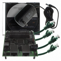
EVALUATION BOARD LAN9311-NU
Manufacturer
SMSC
Series
0133r
Datasheet
1.LAN9311-NU.pdf
(460 pages)
Specifications of EVB9311
Main Purpose
Interface, Ethernet
Embedded
No
Utilized Ic / Part
LAN9311
Primary Attributes
2 Ports, 100BASE-TX/10BASE-T, Managed
Secondary Attributes
2 PHYs with HP Auto-MDIX, Auto- Flow Control, 32-bit CRC, MDI/MDI-X
Lead Free Status / RoHS Status
Lead free / RoHS Compliant
Other names
638-1076


Two Port 10/100 Managed Ethernet Switch with 16-Bit Non-PCI CPU Interface
Datasheet
SMSC LAN9311/LAN9311i
9.5.1
FIELD
FIELD
15:0
7:0
The Filter i Offset register defines the offset in the frame’s destination address field from which the
frames are examined by Filter i.
The Filter i CRC-16 register contains the CRC-16 result of the frame that should pass Filter i.
Table 9.6
Magic Packet Detection
Setting the Magic Packet Enable bit (MPEN) in the
(HMAC_WUCSR)
data reception is disabled, and detection logic within the Host MAC examines received data for a Magic
Packet. The LAN9311/LAN9311i can be programmed to notify the host of the “Magic Packet” detection
with the assertion of the host interrupt (IRQ) or power management event signal (PME). Upon
detection, the Magic Packet Received bit (MPR) in the HMAC_WUCSR register is set. When the host
clears the MPEN bit, the Host MAC will resume normal receive operation. Please refer to
14.3.12, "Host MAC Wake-up Control and Status Register (HMAC_WUCSR)," on page 286
additional information on this register.
In Magic Packet mode, the Host MAC constantly monitors each frame addressed to the node for a
specific Magic Packet pattern. Only packets matching the Host MAC address or broadcast address are
checked for the Magic Packet requirements. Once the address requirement has been met, the Host
MAC checks the received frame for the pattern 48’hFF_FF_FF_FF_FF_FF after the destination and
source address field. The Host MAC then looks in the frame for 16 repetitions of the Host MAC address
without any breaks or interruptions. In case of a break in the 16 address repetitions, the Host MAC
again scans for the 48'hFF_FF_FF_FF_FF_FF pattern in the incoming frame. The 16 repetitions may
be anywhere in the frame but must be preceded by the synchronization stream. The device will also
accept a multicast frame, as long as it detects the 16 duplications of the Host MAC address.
For example, if the Host MAC address is 00h 11h 22h 33h 44h 55h, then the MAC scans for the
following data sequence in an Ethernet frame:
DESCRIPTION
Pattern Offset: The offset of the first byte in the frame on which CRC is checked for wake-up frame
recognition. The minimum value of this field must be 12 since there should be no CRC check for
the destination address and the source address fields. The Host MAC checks the first offset byte
of the frame for CRC and checks to determine whether the frame is a wake-up frame. Offset 0 is
the first byte of the incoming frame's destination address.
DESCRIPTION
Pattern CRC-16: This field contains the 16-bit CRC value from the pattern and the byte mask
programmed to the wake-up filter register function. This value is compared against the CRC
calculated on the incoming frame, and a match indicates the reception of a wakeup frame.
describes the Filter i CRC-16 bit fields.
places the Host MAC in the “Magic Packet” detection mode. In this mode, normal
Table 9.6 Filter i CRC-16 Bit Definitions
Table 9.5 Filter i Offset Bit Definitions
FILTER i OFFSET DESCRIPTION
FILTER i CRC-16 DESCRIPTION
Table 9.5
DATASHEET
119
describes the Filter i Offset bit fields.
Host MAC Wake-up Control and Status Register
Revision 1.7 (06-29-10)
Section
for
Related parts for EVB9311
Image
Part Number
Description
Manufacturer
Datasheet
Request
R


Part Number:
Description:
FAST ETHERNET PHYSICAL LAYER DEVICE
Manufacturer:
SMSC Corporation
Datasheet:
Part Number:
Description:
357-036-542-201 CARDEDGE 36POS DL .156 BLK LOPRO
Manufacturer:
SMSC Corporation
Datasheet:
Part Number:
Description:
357-036-542-201 CARDEDGE 36POS DL .156 BLK LOPRO
Manufacturer:
SMSC Corporation
Datasheet:
Part Number:
Description:
357-036-542-201 CARDEDGE 36POS DL .156 BLK LOPRO
Manufacturer:
SMSC Corporation
Datasheet:
Part Number:
Description:
4-PORT USB2.0 HUB CONTROLLER
Manufacturer:
SMSC Corporation
Datasheet:
Part Number:
Description:
Manufacturer:
SMSC Corporation
Datasheet:
Part Number:
Description:
Manufacturer:
SMSC Corporation
Datasheet:
Part Number:
Description:
FDC37C672ENHANCED SUPER I/O CONTROLLER WITH FAST IR
Manufacturer:
SMSC Corporation
Datasheet:
Part Number:
Description:
COM90C66LJPARCNET Controller/Transceiver with AT Interface and On-Chip RAM
Manufacturer:
SMSC Corporation
Datasheet:
Part Number:
Description:
Manufacturer:
SMSC Corporation
Datasheet:
Part Number:
Description:
Manufacturer:
SMSC Corporation
Datasheet:
Part Number:
Description:
Manufacturer:
SMSC Corporation
Datasheet:
Part Number:
Description:
Manufacturer:
SMSC Corporation
Datasheet: