EVB9311 SMSC, EVB9311 Datasheet - Page 22
EVB9311
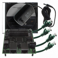
Manufacturer Part Number
EVB9311
Description
EVALUATION BOARD LAN9311-NU
Manufacturer
SMSC
Series
0133r
Datasheet
1.LAN9311-NU.pdf
(460 pages)
Specifications of EVB9311
Main Purpose
Interface, Ethernet
Embedded
No
Utilized Ic / Part
LAN9311
Primary Attributes
2 Ports, 100BASE-TX/10BASE-T, Managed
Secondary Attributes
2 PHYs with HP Auto-MDIX, Auto- Flow Control, 32-bit CRC, MDI/MDI-X
Lead Free Status / RoHS Status
Lead free / RoHS Compliant
Other names
638-1076


Revision 1.7 (06-29-10)
2.2.1
2.2.2
System Clocks/Reset/PME Controller
A clock module contained within the LAN9311/LAN9311i generates all the system clocks required by
the device. This module interfaces directly with the external 25MHz crystal/oscillator to generate the
required clock divisions for each internal module, with the exception of the 1588 clocks, which are
generated in the 1588 Time Stamp Clock/Events module. A 16-bit general purpose timer and 32-bit
free-running clock are provided by this module for general purpose use.
The LAN9311/LAN9311i reset events are categorized as chip-level resets, multi-module resets, and
single-module resets.
A chip-level reset is initiated by assertion of any of the following input events:
A multi-module reset is initiated by assertion of the following:
A single-module reset is initiated by assertion of the following:
The LAN9311/LAN9311i supports numerous power management and wakeup features. The Port 1 &
2 PHYs provide general power-down and energy detect power-down modes, which allow a reduction
in PHY power consumption. The Host MAC provides wake-up frame detection and magic packet
detection modes. The LAN9311/LAN9311i can be programmed to issue an external wake signal (PME)
via several methods, including wake on LAN, wake on link status change (energy detect), and magic
packet wakeup. The PME signal is ideal for triggering system power-up using remote Ethernet wakeup
events.
System Interrupt Controller
The LAN9311/LAN9311i provides a multi-tier programmable interrupt structure which is controlled by
the System Interrupt Controller. At the top level are the
Interrupt Enable Register
various LAN9311/LAN9311i sub-modules. The LAN9311/LAN9311i is capable of generating interrupt
events from the following:
Power-On Reset
nRST Pin Reset
Digital Reset - DIGITAL_RST (bit 0) in the
- Resets all LAN9311/LAN9311i sub-modules except the Ethernet PHYs (Port 1 PHY, Port 2 PHY,
and Virtual PHY)
Soft Reset - SRST (bit 0) in the
- Resets the HBI, Host MAC, and System CSRs below address 100h
Port 2 PHY Reset - PHY2_RST (bit 2) in the
15) in the
- Resets the Port 2 PHY
Port 1 PHY Reset - PHY1_RST (bit 1) in the
15) in the
- Resets the Port 1 PHY
Virtual PHY Reset - VPHY_RST (bit 0) in the
the
Control Register (VPHY_BASIC_CTRL)
- Resets the Virtual PHY
1588 Time Stamp
Switch Fabric
Ethernet PHYs
GPIOs
Host MAC (FIFOs, power management)
Power Management Control Register
Port x PHY Basic Control Register (PHY_BASIC_CONTROL_x)
Port x PHY Basic Control Register (PHY_BASIC_CONTROL_x)
(INT_EN). These registers aggregate and control all interrupts from the
DATASHEET
Hardware Configuration Register (HW_CFG)
22
Two Port 10/100 Managed Ethernet Switch with 16-Bit Non-PCI CPU Interface
(PMT_CTRL), or Reset (bit 15) in the
Reset Control Register (RESET_CTL)
Reset Control Register (RESET_CTL)
Reset Control Register (RESET_CTL)
Reset Control Register
Interrupt Status Register (INT_STS)
(RESET_CTL), (bit 10) in
SMSC LAN9311/LAN9311i
Virtual PHY Basic
or Reset (bit
or Reset (bit
Datasheet
and
Related parts for EVB9311
Image
Part Number
Description
Manufacturer
Datasheet
Request
R


Part Number:
Description:
FAST ETHERNET PHYSICAL LAYER DEVICE
Manufacturer:
SMSC Corporation
Datasheet:
Part Number:
Description:
357-036-542-201 CARDEDGE 36POS DL .156 BLK LOPRO
Manufacturer:
SMSC Corporation
Datasheet:
Part Number:
Description:
357-036-542-201 CARDEDGE 36POS DL .156 BLK LOPRO
Manufacturer:
SMSC Corporation
Datasheet:
Part Number:
Description:
357-036-542-201 CARDEDGE 36POS DL .156 BLK LOPRO
Manufacturer:
SMSC Corporation
Datasheet:
Part Number:
Description:
4-PORT USB2.0 HUB CONTROLLER
Manufacturer:
SMSC Corporation
Datasheet:
Part Number:
Description:
Manufacturer:
SMSC Corporation
Datasheet:
Part Number:
Description:
Manufacturer:
SMSC Corporation
Datasheet:
Part Number:
Description:
FDC37C672ENHANCED SUPER I/O CONTROLLER WITH FAST IR
Manufacturer:
SMSC Corporation
Datasheet:
Part Number:
Description:
COM90C66LJPARCNET Controller/Transceiver with AT Interface and On-Chip RAM
Manufacturer:
SMSC Corporation
Datasheet:
Part Number:
Description:
Manufacturer:
SMSC Corporation
Datasheet:
Part Number:
Description:
Manufacturer:
SMSC Corporation
Datasheet:
Part Number:
Description:
Manufacturer:
SMSC Corporation
Datasheet:
Part Number:
Description:
Manufacturer:
SMSC Corporation
Datasheet: