EVB9311 SMSC, EVB9311 Datasheet - Page 155
EVB9311
Manufacturer Part Number
EVB9311
Description
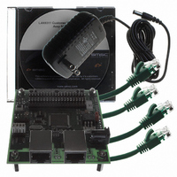
EVALUATION BOARD LAN9311-NU
Manufacturer
SMSC
Series
0133r
Datasheet
1.LAN9311-NU.pdf
(460 pages)
Specifications of EVB9311
Main Purpose
Interface, Ethernet
Embedded
No
Utilized Ic / Part
LAN9311
Primary Attributes
2 Ports, 100BASE-TX/10BASE-T, Managed
Secondary Attributes
2 PHYs with HP Auto-MDIX, Auto- Flow Control, 32-bit CRC, MDI/MDI-X
Lead Free Status / RoHS Status
Lead free / RoHS Compliant
Other names
638-1076


Two Port 10/100 Managed Ethernet Switch with 16-Bit Non-PCI CPU Interface
Datasheet
Chapter 11 IEEE 1588 Hardware Time Stamp Unit
SMSC LAN9311/LAN9311i
11.1
11.1.1
The LAN9311/LAN9311i provides hardware support for the IEEE 1588 Precision Time Protocol (PTP),
allowing clock synchronization with remote Ethernet devices, packet time stamping, and time driven
event generation. Time stamping is supported on all ports, with an individual IEEE 1588 Time Stamp
module connected to each port via the MII bus. Any port may function as a master or a slave clock
per the IEEE 1588 specification, and the LAN9311/LAN9311i as a whole may function as a boundary
clock.
A 64-bit tunable clock is provided that is used as the time source for all IEEE 1588 time stamp related
functions. An IEEE 1588 Clock/Events block provides IEEE 1588 clock comparison based interrupt
generation and time stamp related GPIO event generation. Two LAN9311/LAN9311i GPIO pins
(GPIO[8:9]) can be used to trigger a time stamp capture when configured as an input, or output a
signal from the GPIO based on an IEEE 1588 clock target compare event when configured as an
output.
interface to other LAN9311/LAN9311i functions.
All features of the IEEE 1588 hardware time stamp unit can be monitored and configured via their
respective configuration and status registers. A detailed description of all IEEE 1588 CSRs is included
in
IEEE 1588
IEEE 1588 specifies a Precision Time Protocol (PTP) used by master and slave clock devices to pass
time information in order to achieve clock synchronization. Five network message types are defined:
Only the first four message types (Sync, Delay_Req, Follow_Up, Delay_Resp) are used for clock
synchronization. Using these messages, the protocol software may calculate the offset and network
delay between time stamps, adjusting the slave clock frequency as needed. Refer to the IEEE 1588
protocol for message definitions and proper usage.
A PTP domain is segmented into PTP sub-domains, which are then segmented into PTP
communication paths. Within each PTP communication path there is a maximum of one master clock,
which is the source of time for each slave clock. The determination of which clock is the master and
which clock(s) is(are) the slave(s) is not fixed, but determined by the IEEE 1588 protocol. Similarly,
each PTP sub-domain may have only one master clock, referred to as the Grand Master Clock.
PTP communication paths are conceptually equivalent to Ethernet collision domains and may contain
devices which extend the network. However, unlike Ethernet collision domains, the PTP
communication path does not stop at a network switch, bridge, or router. This leads to a loss of
precision when the network switch/bridge/router introduces a variable delay. Boundary clocks are
defined which conceptually bypass the switch/bridge/router (either physically or via device integration).
Essentially, a boundary clock acts as a slave to an upstream master, and as a master to a down stream
slave. A boundary clock may contain multiple ports, but a maximum of one slave port is permitted.
For more information on the IEEE 1588 protocol, refer to the National Institute of Standards and
Technology IEEE 1588 website:
http://ieee1588.nist.gov/
Functional Overview
Section 14.2.5, "IEEE 1588," on page
Sync
Delay_Req
Follow_Up
Delay_Resp
Management
Section 11.1.2, "Block Diagram"
DATASHEET
describes the various IEEE 1588 related blocks and how they
202.
155
Revision 1.7 (06-29-10)
Related parts for EVB9311
Image
Part Number
Description
Manufacturer
Datasheet
Request
R


Part Number:
Description:
FAST ETHERNET PHYSICAL LAYER DEVICE
Manufacturer:
SMSC Corporation
Datasheet:
Part Number:
Description:
357-036-542-201 CARDEDGE 36POS DL .156 BLK LOPRO
Manufacturer:
SMSC Corporation
Datasheet:
Part Number:
Description:
357-036-542-201 CARDEDGE 36POS DL .156 BLK LOPRO
Manufacturer:
SMSC Corporation
Datasheet:
Part Number:
Description:
357-036-542-201 CARDEDGE 36POS DL .156 BLK LOPRO
Manufacturer:
SMSC Corporation
Datasheet:
Part Number:
Description:
4-PORT USB2.0 HUB CONTROLLER
Manufacturer:
SMSC Corporation
Datasheet:
Part Number:
Description:
Manufacturer:
SMSC Corporation
Datasheet:
Part Number:
Description:
Manufacturer:
SMSC Corporation
Datasheet:
Part Number:
Description:
FDC37C672ENHANCED SUPER I/O CONTROLLER WITH FAST IR
Manufacturer:
SMSC Corporation
Datasheet:
Part Number:
Description:
COM90C66LJPARCNET Controller/Transceiver with AT Interface and On-Chip RAM
Manufacturer:
SMSC Corporation
Datasheet:
Part Number:
Description:
Manufacturer:
SMSC Corporation
Datasheet:
Part Number:
Description:
Manufacturer:
SMSC Corporation
Datasheet:
Part Number:
Description:
Manufacturer:
SMSC Corporation
Datasheet:
Part Number:
Description:
Manufacturer:
SMSC Corporation
Datasheet: