EVB9311 SMSC, EVB9311 Datasheet - Page 36
EVB9311
Manufacturer Part Number
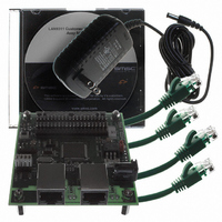
EVB9311
Description
EVALUATION BOARD LAN9311-NU
Manufacturer
SMSC
Series
0133r
Datasheet
1.LAN9311-NU.pdf
(460 pages)
Specifications of EVB9311
Main Purpose
Interface, Ethernet
Embedded
No
Utilized Ic / Part
LAN9311
Primary Attributes
2 Ports, 100BASE-TX/10BASE-T, Managed
Secondary Attributes
2 PHYs with HP Auto-MDIX, Auto- Flow Control, 32-bit CRC, MDI/MDI-X
Lead Free Status / RoHS Status
Lead free / RoHS Compliant
Other names
638-1076


Chapter 4 Clocking, Resets, and Power Management
Revision 1.7 (06-29-10)
4.1
4.2
The LAN9311/LAN9311i includes a clock module which provides generation of all system clocks as
required by the various sub-modules of the device. The LAN9311/LAN9311i requires a fixed-frequency
25MHz clock source for use by the internal clock oscillator and PLL. This is typically provided by
attaching a 25MHz crystal to the XI and XO pins as specified in
page
clock source. If a single-ended source is selected, the clock input must run continuously for normal
device operation. The internal PLL generates a fixed 200MHz base clock which is used to derive all
LAN9311/LAN9311i sub-system clocks.
In addition to the sub-system clocks, the clock module is also responsible for generating the clocks
used for the general purpose timer and free-running clock. Refer to
Timer & Free-Running Clock," on page 162
Note: Crystal specifications are provided in
The LAN9311/LAN9311i provides multiple hardware and software reset sources, which allow varying
levels of the LAN9311/LAN9311i to be reset. All resets can be categorized into three reset types as
described in the following sections:
The LAN9311/LAN9311i supports the use of configuration straps to allow automatic custom
configurations of various LAN9311/LAN9311i parameters. These configuration strap values are set
upon de-assertion of all chip-level resets and can be used to easily set the default parameters of the
chip at power-on or pin (nRST) reset. Refer to
detailed information on the usage of these straps.
Note: The LAN9311/LAN9311i EEPROM Loader is run upon a power-on reset, nRST pin reset, and
Table 4.1
following sections for detailed information on each of these reset types.
Clocks
Resets
—Power-On Reset (POR)
—nRST Pin Reset
—Digital Reset (DIGITAL_RST)
—Soft Reset (SRST)
—Port 2 PHY Reset
—Port 1 PHY Reset
—Virtual PHY Reset
Chip-Level Resets
Multi-Module Resets
Single-Module Resets
454. Optionally, this clock can be provided by driving the XI input pin with a single-ended 25MHz
on page
digital reset. Refer to
information.
summarizes the effect of the various reset sources on the LAN9311/LAN9311i. Refer to the
454.
Section 10.2.4, "EEPROM Loader," on page 150
DATASHEET
36
Two Port 10/100 Managed Ethernet Switch with 16-Bit Non-PCI CPU Interface
for additional details.
Table 15.15, “LAN9311/LAN9311iCrystal Specifications,”
Section 4.2.4, "Configuration Straps," on page 40
Section 15.6, "Clock Circuit," on
Chapter 12, "General Purpose
SMSC LAN9311/LAN9311i
for additional
Datasheet
for
Related parts for EVB9311
Image
Part Number
Description
Manufacturer
Datasheet
Request
R


Part Number:
Description:
FAST ETHERNET PHYSICAL LAYER DEVICE
Manufacturer:
SMSC Corporation
Datasheet:
Part Number:
Description:
357-036-542-201 CARDEDGE 36POS DL .156 BLK LOPRO
Manufacturer:
SMSC Corporation
Datasheet:
Part Number:
Description:
357-036-542-201 CARDEDGE 36POS DL .156 BLK LOPRO
Manufacturer:
SMSC Corporation
Datasheet:
Part Number:
Description:
357-036-542-201 CARDEDGE 36POS DL .156 BLK LOPRO
Manufacturer:
SMSC Corporation
Datasheet:
Part Number:
Description:
4-PORT USB2.0 HUB CONTROLLER
Manufacturer:
SMSC Corporation
Datasheet:
Part Number:
Description:
Manufacturer:
SMSC Corporation
Datasheet:
Part Number:
Description:
Manufacturer:
SMSC Corporation
Datasheet:
Part Number:
Description:
FDC37C672ENHANCED SUPER I/O CONTROLLER WITH FAST IR
Manufacturer:
SMSC Corporation
Datasheet:
Part Number:
Description:
COM90C66LJPARCNET Controller/Transceiver with AT Interface and On-Chip RAM
Manufacturer:
SMSC Corporation
Datasheet:
Part Number:
Description:
Manufacturer:
SMSC Corporation
Datasheet:
Part Number:
Description:
Manufacturer:
SMSC Corporation
Datasheet:
Part Number:
Description:
Manufacturer:
SMSC Corporation
Datasheet:
Part Number:
Description:
Manufacturer:
SMSC Corporation
Datasheet: