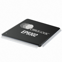
EP9302-CQZ Cirrus Logic Inc, EP9302-CQZ Datasheet - Page 403

EP9302-CQZ
Manufacturer Part Number
EP9302-CQZ
Description
IC ARM9 SOC PROCESSOR 208LQFP
Manufacturer
Cirrus Logic Inc
Series
EP9r
Datasheets
1.EP9307-CRZ.pdf
(824 pages)
2.EP9302-IQZ.pdf
(42 pages)
3.EP9302-IQZ.pdf
(4 pages)
4.EP9302-IQZ.pdf
(40 pages)
Specifications of EP9302-CQZ
Program Memory Type
ROMless
Package / Case
208-LQFP
Core Processor
ARM9
Core Size
16/32-Bit
Speed
200MHz
Connectivity
EBI/EMI, Ethernet, I²C, IrDA, SPI, UART/USART, USB
Peripherals
AC'97, DMA, I²:S, LED, MaverickKey, POR, PWM, WDT
Number Of I /o
19
Ram Size
32K x 8
Voltage - Supply (vcc/vdd)
1.65 V ~ 3.6 V
Data Converters
A/D 5x12b
Oscillator Type
External
Operating Temperature
0°C ~ 70°C
Processor Series
EP93xx
Core
ARM920T
Data Bus Width
32 bit
Data Ram Size
16 bit
Interface Type
USB, USART, SPI
Maximum Clock Frequency
200 MHz
Number Of Programmable I/os
37
Mounting Style
SMD/SMT
3rd Party Development Tools
MDK-ARM, RL-ARM, ULINK2
Development Tools By Supplier
EDB9302A-Z
Controller Family/series
(ARM9)
No. Of I/o's
19
Ram Memory Size
16MB
Cpu Speed
200MHz
No. Of Timers
4
Embedded Interface Type
AC97, I2S, SPI, UART, USB
Rohs Compliant
Yes
Lead Free Status / RoHS Status
Lead free / RoHS Compliant
For Use With
598-1132 - KIT DEVELOPMENT EP9302 ARM9
Eeprom Size
-
Program Memory Size
-
Lead Free Status / Rohs Status
Lead free / RoHS Compliant
Other names
598-1137
Available stocks
Company
Part Number
Manufacturer
Quantity
Price
Company:
Part Number:
EP9302-CQZ
Manufacturer:
Cirrus
Quantity:
3 295
Company:
Part Number:
EP9302-CQZ
Manufacturer:
ALTERA
Quantity:
672
Part Number:
EP9302-CQZ
Manufacturer:
CYPRESS/赛普拉斯
Quantity:
20 000
- EP9307-CRZ PDF datasheet
- EP9302-IQZ PDF datasheet #2
- EP9302-IQZ PDF datasheet #3
- EP9302-IQZ PDF datasheet #4
- Current page: 403 of 824
- Download datasheet (13Mb)
DS785UM1
10.1.9.2 Data Transfer Initiation and Termination
The DMA Controller initiates data transfer in the receive direction when:
The DMA Controller stops data transfers in the receive direction and moves onto the next
buffer when:
The DMA Controller initiates data transfers in the transmit direction when an Un-packer unit
becomes empty.
The DMA Controller stops data transfer in the transmit direction when:
Note: This refers to bytes entering the data packer and not just data transmitted over the AHB
• A packer unit becomes full
• A packer unit, dependent on the next address access, contains enough data for an
• RxEnd signal is asserted to indicate end of received data or received error.
• The number of bytes transferred from a receive peripheral reaches MAXCNTx.
• TxEnd signal is asserted to indicate that the transfer is the last in the transmit data
• TxTC signal asserted by DMA Controller to indicate to the peripheral that the transfer is
• Bursting across buffers cannot be carried out in either transmit or receive directions. The
unaligned byte/word access.
stream. Any data remaining in the Un-packer unit is considered invalid and flushed. At
this point, the Channel Status Register will be updated and next buffer defined.
the last as the byte count limit has been reached. At this point, the Channel Status
Register will be updated and next buffer defined.
reason is that buffer pairs may not be contiguous, as required by HTRANS SEQ transfer
type (where address = address of previous transfer + size in bytes).
any valid data in the receive packer to main memory. If RxEnd signals the end of
received data then all data which is present in the receive packer gets flushed to
memory. If RxEnd signals an error in receive data, and if the ICE bit (Ignore Channel
Error) is not set, then the erroneous byte is not written to memory. Only valid bytes are
written. If ICE bit is set then the erroneous byte is written to memory. The DMA will
update the Channel Status Register, generating a system interrupt which informs the
processor that a new buffer needs to be allocated, and DMA will also indicate
(NEXTBUFFER field) which pair of buffer descriptor registers (MAXCNTx, BASEx)
should be used for the next buffer.
No matter what the alignment up to now, this causes the AHB Master interface to write
bus (that is, has same effect as RxEnd signal generated by the peripheral). The DMA
Controller asserts RxTC to the peripheral to indicate this condition. The DMA will update
the Channel Status Register, generating a system interrupt, which informs the processor
that a new buffer needs to be allocated and DMA will also indicate (NEXTBUFFER field)
which pair of buffer descriptor registers (MAXCNTx, BASEx) should be used for the next
buffer.
Copyright 2007 Cirrus Logic
EP93xx User’s Guide
DMA Controller
10-9
10
Related parts for EP9302-CQZ
Image
Part Number
Description
Manufacturer
Datasheet
Request
R

Part Number:
Description:
IC ARM9 SOC PROCESSOR 208LQFP
Manufacturer:
Cirrus Logic Inc
Datasheet:

Part Number:
Description:
High Performance, Entry Level ARM9 SoC
Manufacturer:
Cirrus Logic Inc

Part Number:
Description:
MCU, MPU & DSP Development Tools Eval Bd Hgh-Prfrmnc ARM9 SOC Processor
Manufacturer:
Cirrus Logic Inc
Datasheet:

Part Number:
Description:
Development Kit
Manufacturer:
Cirrus Logic Inc
Datasheet:

Part Number:
Description:
Development Kit
Manufacturer:
Cirrus Logic Inc
Datasheet:

Part Number:
Description:
High-efficiency PFC + Fluorescent Lamp Driver Reference Design
Manufacturer:
Cirrus Logic Inc
Datasheet:

Part Number:
Description:
Development Kit
Manufacturer:
Cirrus Logic Inc
Datasheet:

Part Number:
Description:
Development Kit
Manufacturer:
Cirrus Logic Inc
Datasheet:

Part Number:
Description:
Development Kit
Manufacturer:
Cirrus Logic Inc
Datasheet:

Part Number:
Description:
Development Kit
Manufacturer:
Cirrus Logic Inc
Datasheet:

Part Number:
Description:
Development Kit
Manufacturer:
Cirrus Logic Inc
Datasheet:

Part Number:
Description:
Ref Bd For Speakerbar MSA & DSP Products
Manufacturer:
Cirrus Logic Inc


