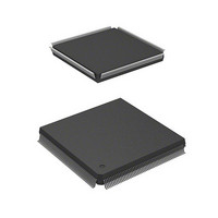
HD6417750RF240DV Renesas Electronics America, HD6417750RF240DV Datasheet - Page 392

HD6417750RF240DV
Manufacturer Part Number
HD6417750RF240DV
Description
MPU 3V 16K I-TEMP,PB-FREE 208-QF
Manufacturer
Renesas Electronics America
Series
SuperH® SH7750r
Datasheet
1.D6417750RBP240DV.pdf
(1164 pages)
Specifications of HD6417750RF240DV
Core Processor
SH-4
Core Size
32-Bit
Speed
240MHz
Connectivity
EBI/EMI, FIFO, SCI, SmartCard
Peripherals
DMA, POR, WDT
Number Of I /o
28
Program Memory Type
ROMless
Ram Size
48K x 8
Voltage - Supply (vcc/vdd)
1.4 V ~ 1.6 V
Oscillator Type
External
Operating Temperature
-40°C ~ 85°C
Package / Case
208-QFP
Lead Free Status / RoHS Status
Lead free / RoHS Compliant
Eeprom Size
-
Program Memory Size
-
Data Converters
-
Available stocks
Company
Part Number
Manufacturer
Quantity
Price
Company:
Part Number:
HD6417750RF240DV
Manufacturer:
HITACHI
Quantity:
7 287
- Current page: 392 of 1164
- Download datasheet (7Mb)
Section 10 Clock Oscillation Circuits
3. Make a transition to standby mode, and stop the clock, by executing a SLEEP instruction.
4. The WDT starts counting on detection of an NMI signal transition edge or an interrupt.
5. When the WDT count overflows, the CPG starts clock supply and the processor resumes
6. The counter stops at a value of H'00–H'01. The value at which the counter stops depends on
10.9.2
The WDT is used in a frequency change using the PLL. It is not used when the frequency is
changed simply by making a frequency divider switch.
1. Be sure to clear the TME bit in the WTCSR register to 0 before making a frequency change. If
2. Select the count clock to be used with bits CKS2–CKS0 in the WTCSR register, and set the
3. When the frequency control register (FRQCR) is modified, the clock stops, and the standby
4. When the WDT count overflows, the CPG starts clock supply and the processor resumes
5. The counter stops at a value of H'00–H'01. The value at which the counter stops depends on
6. When re-setting WTCNT immediately after modifying the frequency control register
10.9.3
1. Set the WT/IT bit in the WTCSR register to 1, select the type of reset with the RSTS bit, and
2. When the TME bit in the WTCSR register is set to 1, the count starts in watchdog timer mode.
3. During operation in watchdog timer mode, write H'00 to the counter periodically so that it does
Rev.7.00 Oct. 10, 2008 Page 306 of 1074
REJ09B0366-0700
overflows is at least as long as the clock oscillation stabilization time. For details of the clock
oscillation stabilization time, see section 22.3.1, Clock and Control Signal Timing.
operation. The WOVF flag in the WTCSR register is not set at this time.
the clock ratio.
the TME bit is set to 1, an inadvertent reset or interval timer interrupt may be caused when the
count overflows.
initial value in the WTCNT counter. Make these settings so that the time until the count
overflows is at least as long as the clock oscillation stabilization time. For details of the clock
oscillation stabilization time, see section 22.3.1, Clock and Control Signal Timing.
state is entered temporarily. The WDT starts counting.
operation. The WOVF flag in the WTCSR register is not set at this time.
the count clock with bits CKS2–CKS0, and set the initial value in the WTCNT counter.
not overflow.
the clock ratio.
(FRQCR), first read the counter and confirm that its value is as described in step 5 above.
Frequency Changing Procedure
Using Watchdog Timer Mode
Related parts for HD6417750RF240DV
Image
Part Number
Description
Manufacturer
Datasheet
Request
R

Part Number:
Description:
KIT STARTER FOR M16C/29
Manufacturer:
Renesas Electronics America
Datasheet:

Part Number:
Description:
KIT STARTER FOR R8C/2D
Manufacturer:
Renesas Electronics America
Datasheet:

Part Number:
Description:
R0K33062P STARTER KIT
Manufacturer:
Renesas Electronics America
Datasheet:

Part Number:
Description:
KIT STARTER FOR R8C/23 E8A
Manufacturer:
Renesas Electronics America
Datasheet:

Part Number:
Description:
KIT STARTER FOR R8C/25
Manufacturer:
Renesas Electronics America
Datasheet:

Part Number:
Description:
KIT STARTER H8S2456 SHARPE DSPLY
Manufacturer:
Renesas Electronics America
Datasheet:

Part Number:
Description:
KIT STARTER FOR R8C38C
Manufacturer:
Renesas Electronics America
Datasheet:

Part Number:
Description:
KIT STARTER FOR R8C35C
Manufacturer:
Renesas Electronics America
Datasheet:

Part Number:
Description:
KIT STARTER FOR R8CL3AC+LCD APPS
Manufacturer:
Renesas Electronics America
Datasheet:

Part Number:
Description:
KIT STARTER FOR RX610
Manufacturer:
Renesas Electronics America
Datasheet:

Part Number:
Description:
KIT STARTER FOR R32C/118
Manufacturer:
Renesas Electronics America
Datasheet:

Part Number:
Description:
KIT DEV RSK-R8C/26-29
Manufacturer:
Renesas Electronics America
Datasheet:

Part Number:
Description:
KIT STARTER FOR SH7124
Manufacturer:
Renesas Electronics America
Datasheet:

Part Number:
Description:
KIT STARTER FOR H8SX/1622
Manufacturer:
Renesas Electronics America
Datasheet:

Part Number:
Description:
KIT DEV FOR SH7203
Manufacturer:
Renesas Electronics America
Datasheet:


