ATEVK1105 Atmel, ATEVK1105 Datasheet - Page 99
ATEVK1105
Manufacturer Part Number
ATEVK1105
Description
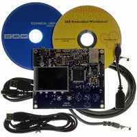
KIT EVAL FOR AT32UC3A0
Manufacturer
Atmel
Series
AVR®32r
Type
MCUr
Datasheets
1.ATAVRONE-PROBECBL.pdf
(16 pages)
2.ATEVK1104.pdf
(826 pages)
3.ATEVK1105.pdf
(28 pages)
Specifications of ATEVK1105
Contents
Evaluation Board, Software and Documentation
Processor To Be Evaluated
AT32UC3A0512
Processor Series
AVR
Data Bus Width
32 bit
Interface Type
USART, TWI, USB, SPI, Ethernet
Operating Supply Voltage
3.3 V
Silicon Manufacturer
Atmel
Core Architecture
AVR
Core Sub-architecture
AVR UC3
Silicon Core Number
AT32UC3A0512
Silicon Family Name
AVR
Kit Contents
Board CD Docs
Rohs Compliant
Yes
For Use With/related Products
AT32UC3A0
Lead Free Status / RoHS Status
Lead free / RoHS Compliant


16. Interrupt Controller (INTC)
16.1
16.2
16.3
32058J–AVR32–04/11
Description
Block Diagram
Operation
Rev: 1.0.1.1
The INTC collects interrupt requests from the peripherals, prioritizes them, and delivers an inter-
rupt request and an autovector to the CPU. The AVR32 architecture supports 4 priority levels for
regular, maskable interrupts, and a Non-Maskable Interrupt (NMI).
The INTC supports up to 64 groups of interrupts. Each group can have up to 32 interrupt request
lines, these lines are connected to the peripherals. Each group has an Interrupt Priority Register
(IPR) and an Interrupt Request Register (IRR). The IPRs are used to assign a priority level and
an autovector to each group, and the IRRs are used to identify the active interrupt request within
each group. If a group has only one interrupt request line, an active interrupt group uniquely
identifies the active interrupt request line, and the corresponding IRR is not needed. The INTC
also provides one Interrupt Cause Register (ICR) per priority level. These registers identify the
group that has a pending interrupt of the corresponding priority level. If several groups have an
pending interrupt of the same level, the group with the lowest number takes priority.
Figure 16-1 on page 99
can be accessed via the Peripheral Bus (PB). The interrupt requests from the peripherals
(IREQn) and the NMI are input on the left side of the figure. Signals to and from the CPU are on
the right side of the figure.
Figure 16-1. Overview of the Interrupt Controller
All of the incoming interrupt requests (IREQs) are sampled into the corresponding Interrupt
Request Register (IRR). The IRRs must be accessed to identify which IREQ within a group that
is active. If several IREQs within the same group is active, the interrupt service routine must pri-
NMIREQ
IREQ63
IREQ34
IREQ33
IREQ32
IREQ31
IREQ2
IREQ1
IREQ0
IRR registers
Interrupt Controller
IRRn
IRR1
IRR0
OR
OR
OR
GrpReqN
GrpReq1
GrpReq0
gives an overview of the INTC. The grey boxes represent registers that
Request
masking
ValReqN
ValReq1
ValReq0
IPRn
IPR1
IPR0
IPR registers
INT_level, offset
INT_level, offset
INT_level, offset
ICR registers
AT32UC3A
AUTOVECTOR
INTLEVEL
Masks
I[3-0]M
SREG
masks
CPU
GM
99
Related parts for ATEVK1105
Image
Part Number
Description
Manufacturer
Datasheet
Request
R

Part Number:
Description:
DEV KIT FOR AVR/AVR32
Manufacturer:
Atmel
Datasheet:

Part Number:
Description:
INTERVAL AND WIPE/WASH WIPER CONTROL IC WITH DELAY
Manufacturer:
ATMEL Corporation
Datasheet:
Part Number:
Description:
Low-Voltage Voice-Switched IC for Hands-Free Operation
Manufacturer:
ATMEL Corporation
Datasheet:
Part Number:
Description:
MONOLITHIC INTEGRATED FEATUREPHONE CIRCUIT
Manufacturer:
ATMEL Corporation
Datasheet:
Part Number:
Description:
AM-FM Receiver IC U4255BM-M
Manufacturer:
ATMEL Corporation
Datasheet:
Part Number:
Description:
Monolithic Integrated Feature Phone Circuit
Manufacturer:
ATMEL Corporation
Datasheet:
Part Number:
Description:
Multistandard Video-IF and Quasi Parallel Sound Processing
Manufacturer:
ATMEL Corporation
Datasheet:
Part Number:
Description:
High-performance EE PLD
Manufacturer:
ATMEL Corporation
Datasheet:
Part Number:
Description:
8-bit Flash Microcontroller
Manufacturer:
ATMEL Corporation
Datasheet:
Part Number:
Description:
2-Wire Serial EEPROM
Manufacturer:
ATMEL Corporation
Datasheet: