ATEVK1105 Atmel, ATEVK1105 Datasheet - Page 329
ATEVK1105
Manufacturer Part Number
ATEVK1105
Description
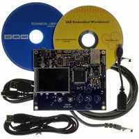
KIT EVAL FOR AT32UC3A0
Manufacturer
Atmel
Series
AVR®32r
Type
MCUr
Datasheets
1.ATAVRONE-PROBECBL.pdf
(16 pages)
2.ATEVK1104.pdf
(826 pages)
3.ATEVK1105.pdf
(28 pages)
Specifications of ATEVK1105
Contents
Evaluation Board, Software and Documentation
Processor To Be Evaluated
AT32UC3A0512
Processor Series
AVR
Data Bus Width
32 bit
Interface Type
USART, TWI, USB, SPI, Ethernet
Operating Supply Voltage
3.3 V
Silicon Manufacturer
Atmel
Core Architecture
AVR
Core Sub-architecture
AVR UC3
Silicon Core Number
AT32UC3A0512
Silicon Family Name
AVR
Kit Contents
Board CD Docs
Rohs Compliant
Yes
For Use With/related Products
AT32UC3A0
Lead Free Status / RoHS Status
Lead free / RoHS Compliant


26.7.5.7
26.7.6
26.7.6.1
32058J–AVR32–04/11
IrDA Mode
Protocol T = 1
IrDA Modulation
MAX_ITERATION is reached, the character is considered as correct, an acknowledge is sent on
the line and the ITERATION bit in the Channel Status Register is set.
When operating in ISO7816 protocol T = 1, the transmission is similar to an asynchronous for-
mat with only one stop bit. The parity is generated when transmitting and checked when
receiving. Parity error detection sets the PARE bit in the Channel Status Register (CSR).
The USART features an IrDA mode supplying half-duplex point-to-point wireless communica-
tion. It embeds the modulator and demodulator which allows a glueless connection to the
infrared transceivers, as shown in
are compliant with the IrDA specification version 1.1 and support data transfer speeds ranging
from 2.4 Kb/s to 115.2 Kb/s.
The USART IrDA mode is enabled by setting the MODE field in the Mode Register (MR) to the
value 0x8. The IrDA Filter Register (IFR) allows configuring the demodulator filter. The USART
transmitter and receiver operate in a normal asynchronous mode and all parameters are acces-
sible. Note that the modulator and the demodulator are activated.
Figure 26-33. Connection to IrDA Transceivers
The receiver and the transmitter must be enabled or disabled according to the direction of the
transmission to be managed.
For baud rates up to and including 115.2 Kbits/sec, the RZI modulation scheme is used. “0” is
represented by a light pulse of 3/16th of a bit time. Some examples of signal pulse duration are
shown in
Table 26-9.
Baud Rate
2.4 Kb/s
9.6 Kb/s
19.2 Kb/s
Table 26-9 on page
IrDA Pulse Duration
Transmitter
Receiver
USART
329.
Demodulator
Figure 26-33 on page
Modulator
Pulse Duration (3/16)
78.13 µs
19.53 µs
9.77 µs
RXD
TXD
329. The modulator and demodulator
RX
TX
Transceivers
AT32UC3A
IrDA
329
Related parts for ATEVK1105
Image
Part Number
Description
Manufacturer
Datasheet
Request
R

Part Number:
Description:
DEV KIT FOR AVR/AVR32
Manufacturer:
Atmel
Datasheet:

Part Number:
Description:
INTERVAL AND WIPE/WASH WIPER CONTROL IC WITH DELAY
Manufacturer:
ATMEL Corporation
Datasheet:
Part Number:
Description:
Low-Voltage Voice-Switched IC for Hands-Free Operation
Manufacturer:
ATMEL Corporation
Datasheet:
Part Number:
Description:
MONOLITHIC INTEGRATED FEATUREPHONE CIRCUIT
Manufacturer:
ATMEL Corporation
Datasheet:
Part Number:
Description:
AM-FM Receiver IC U4255BM-M
Manufacturer:
ATMEL Corporation
Datasheet:
Part Number:
Description:
Monolithic Integrated Feature Phone Circuit
Manufacturer:
ATMEL Corporation
Datasheet:
Part Number:
Description:
Multistandard Video-IF and Quasi Parallel Sound Processing
Manufacturer:
ATMEL Corporation
Datasheet:
Part Number:
Description:
High-performance EE PLD
Manufacturer:
ATMEL Corporation
Datasheet:
Part Number:
Description:
8-bit Flash Microcontroller
Manufacturer:
ATMEL Corporation
Datasheet:
Part Number:
Description:
2-Wire Serial EEPROM
Manufacturer:
ATMEL Corporation
Datasheet: