ATEVK1105 Atmel, ATEVK1105 Datasheet - Page 523
ATEVK1105
Manufacturer Part Number
ATEVK1105
Description
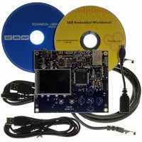
KIT EVAL FOR AT32UC3A0
Manufacturer
Atmel
Series
AVR®32r
Type
MCUr
Datasheets
1.ATAVRONE-PROBECBL.pdf
(16 pages)
2.ATEVK1104.pdf
(826 pages)
3.ATEVK1105.pdf
(28 pages)
Specifications of ATEVK1105
Contents
Evaluation Board, Software and Documentation
Processor To Be Evaluated
AT32UC3A0512
Processor Series
AVR
Data Bus Width
32 bit
Interface Type
USART, TWI, USB, SPI, Ethernet
Operating Supply Voltage
3.3 V
Silicon Manufacturer
Atmel
Core Architecture
AVR
Core Sub-architecture
AVR UC3
Silicon Core Number
AT32UC3A0512
Silicon Family Name
AVR
Kit Contents
Board CD Docs
Rohs Compliant
Yes
For Use With/related Products
AT32UC3A0
Lead Free Status / RoHS Status
Lead free / RoHS Compliant


30.7.3.3
30.7.3.4
30.7.3.5
30.7.3.6
32058J–AVR32–04/11
Device Detection
Pipe Activation
USB Reset
Pipe Reset
The controller enters the Suspend state when the USB bus is in a “Suspend” state, i.e. when the
host mode does not generate the “Start of Frame”. In this state, the USB consumption is mini-
mal. The host mode exits the Suspend state when starting to generate the SOF over the USB
line.
A device is detected by the USB controller host mode when D+ or D- is no longer tied low, i.e.
when the device D+ or D- pull-up resistor is connected. To enable this detection, the host con-
troller has to provide the VBus power supply to the device by setting the VBUSRQ bit (by setting
the VBUSRQS bit).
The device disconnection is detected by the host controller when both D+ and D- are pulled
down.
The USB controller sends a USB bus reset when the firmware sets the RESET bit. The USB
Reset Sent interrupt (RSTI) is raised when the USB reset has been sent. In this case, all the
pipes are disabled and de-allocated.
If the bus was previously in a “Suspend” state (SOFE = 0), the USB controller automatically
switches it to the “Resume” state, the Host Wake-Up interrupt (HWUPI) is raised and the SOFE
bit is set by hardware in order to generate SOFs immediately after the USB reset.
A pipe can be reset at any time by setting its PRSTX bit in the UPRST register. This is recom-
mended before using a pipe upon hardware reset or when a USB bus reset has been sent. This
resets:
The pipe configuration remains active and the pipe is still enabled.
The pipe reset may be associated with a clear of the data toggle sequence. This can be
achieved by setting the RSTDT bit (by setting the RSTDTS bit).
In the end, the firmware has to clear the PRSTX bit to complete the reset operation and to start
using the FIFO.
The pipe is maintained inactive and reset (see
long as it is disabled (PENX = 0). The Data Toggle Sequence bit-field (DTSEQ) is also reset.
The algorithm represented on
•the internal state machine of this pipe;
•the receive and transmit bank FIFO counters;
•all the registers of this pipe (UPCFGX, UPSTAX, UPCONX), except its configuration (ALLOC,
PBK, PSIZE, PTOKEN, PTYPE, PEPNUM, INTFRQ) and its Data Toggle Sequence bit-field
(DTSEQ).
Figure 30-24
must be followed in order to activate a pipe.
Section 30.7.3.5 on page 523
AT32UC3A
for more details) as
523
Related parts for ATEVK1105
Image
Part Number
Description
Manufacturer
Datasheet
Request
R

Part Number:
Description:
DEV KIT FOR AVR/AVR32
Manufacturer:
Atmel
Datasheet:

Part Number:
Description:
INTERVAL AND WIPE/WASH WIPER CONTROL IC WITH DELAY
Manufacturer:
ATMEL Corporation
Datasheet:
Part Number:
Description:
Low-Voltage Voice-Switched IC for Hands-Free Operation
Manufacturer:
ATMEL Corporation
Datasheet:
Part Number:
Description:
MONOLITHIC INTEGRATED FEATUREPHONE CIRCUIT
Manufacturer:
ATMEL Corporation
Datasheet:
Part Number:
Description:
AM-FM Receiver IC U4255BM-M
Manufacturer:
ATMEL Corporation
Datasheet:
Part Number:
Description:
Monolithic Integrated Feature Phone Circuit
Manufacturer:
ATMEL Corporation
Datasheet:
Part Number:
Description:
Multistandard Video-IF and Quasi Parallel Sound Processing
Manufacturer:
ATMEL Corporation
Datasheet:
Part Number:
Description:
High-performance EE PLD
Manufacturer:
ATMEL Corporation
Datasheet:
Part Number:
Description:
8-bit Flash Microcontroller
Manufacturer:
ATMEL Corporation
Datasheet:
Part Number:
Description:
2-Wire Serial EEPROM
Manufacturer:
ATMEL Corporation
Datasheet: