ATEVK1105 Atmel, ATEVK1105 Datasheet - Page 497
ATEVK1105
Manufacturer Part Number
ATEVK1105
Description
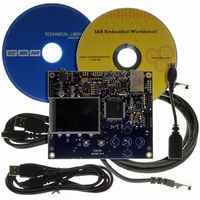
KIT EVAL FOR AT32UC3A0
Manufacturer
Atmel
Series
AVR®32r
Type
MCUr
Datasheets
1.ATAVRONE-PROBECBL.pdf
(16 pages)
2.ATEVK1104.pdf
(826 pages)
3.ATEVK1105.pdf
(28 pages)
Specifications of ATEVK1105
Contents
Evaluation Board, Software and Documentation
Processor To Be Evaluated
AT32UC3A0512
Processor Series
AVR
Data Bus Width
32 bit
Interface Type
USART, TWI, USB, SPI, Ethernet
Operating Supply Voltage
3.3 V
Silicon Manufacturer
Atmel
Core Architecture
AVR
Core Sub-architecture
AVR UC3
Silicon Core Number
AT32UC3A0512
Silicon Family Name
AVR
Kit Contents
Board CD Docs
Rohs Compliant
Yes
For Use With/related Products
AT32UC3A0
Lead Free Status / RoHS Status
Lead free / RoHS Compliant


30. USB On-The-Go Interface (USBB)
30.1
30.2
Table 30-1.
32058J–AVR32–04/11
Pipe/Endpoint
Features
Description
0
1
2
3
4
5
6
Description of USB Pipes/Endpoints
Mnemonic
Rev: 3.1.1.1
•
•
•
•
•
•
•
The Universal Serial Bus (USB) MCU device complies with the Universal Serial Bus (USB) 2.0
specification, but it does NOT feature high-speed USB (480 Mbit/s).
Each pipe/endpoint can be configured in one of several transfer types. It can be associated with
one or more banks of a dual-port RAM used to store the current data payload. If several banks
are used (“ping-pong” mode), then one DPRAM bank is read or written by the CPU or the DMA
while the other is read or written by the USB macro core. This feature is mandatory for isochro-
nous pipes/endpoints.
Table 30-1
PEP0
PEP1
PEP2
PEP3
PEP4
PEP5
PEP6
The theoretical maximal pipe/endpoint configuration (1600 bytes) exceeds the real DPRAM size
(960 bytes). The user needs to be aware of this when configuring pipes/endpoints. To fully use
the 960 bytes of DPRAM, the user could for example use the configuration described in
30-2.
Table 30-2.
USB 2.0 Compliant, Full-/Low-Speed (FS/LS) and On-The-Go (OTG), 12 Mbit/s
7 Pipes/Endpoints
960 bytes of Embedded Dual-Port RAM (DPRAM) for Pipes/Endpoints
Up to 2 Memory Banks per Pipe/Endpoint (Not for Control Pipe/Endpoint)
Flexible Pipe/Endpoint Configuration and Management with Dedicated DMA Channels
On-Chip Transceivers Including Pull-Ups/Pull-downs.
On-Chip OTG pad including VBUS analog comparator
Pipe/Endpoint
0
1
2
3
describes the hardware configuration of the USB MCU device.
Example of Configuration of Pipes/Endpoints Using the Whole DPRAM
Max. Size
64 bytes
64 bytes
64 bytes
bytes
bytes
bytes
bytes
Mnemonic
PEP0
PEP1
PEP2
PEP3
Max. Nb. Banks
1
64 bytes
64 bytes
64 bytes
64 bytes
Size
DMA
N
Y
Y
Y
Y
Y
Y
Nb. Banks
1
2
2
1
Isochronous/Bulk/Interrupt
Isochronous/Bulk/Interrupt
Isochronous/Bulk/Interrupt
Isochronous/Bulk/Interrupt
Bulk/Interrupt
Bulk/Interrupt
AT32UC3A
Control
Type
Table
497
Related parts for ATEVK1105
Image
Part Number
Description
Manufacturer
Datasheet
Request
R

Part Number:
Description:
DEV KIT FOR AVR/AVR32
Manufacturer:
Atmel
Datasheet:

Part Number:
Description:
INTERVAL AND WIPE/WASH WIPER CONTROL IC WITH DELAY
Manufacturer:
ATMEL Corporation
Datasheet:
Part Number:
Description:
Low-Voltage Voice-Switched IC for Hands-Free Operation
Manufacturer:
ATMEL Corporation
Datasheet:
Part Number:
Description:
MONOLITHIC INTEGRATED FEATUREPHONE CIRCUIT
Manufacturer:
ATMEL Corporation
Datasheet:
Part Number:
Description:
AM-FM Receiver IC U4255BM-M
Manufacturer:
ATMEL Corporation
Datasheet:
Part Number:
Description:
Monolithic Integrated Feature Phone Circuit
Manufacturer:
ATMEL Corporation
Datasheet:
Part Number:
Description:
Multistandard Video-IF and Quasi Parallel Sound Processing
Manufacturer:
ATMEL Corporation
Datasheet:
Part Number:
Description:
High-performance EE PLD
Manufacturer:
ATMEL Corporation
Datasheet:
Part Number:
Description:
8-bit Flash Microcontroller
Manufacturer:
ATMEL Corporation
Datasheet:
Part Number:
Description:
2-Wire Serial EEPROM
Manufacturer:
ATMEL Corporation
Datasheet: