ATEVK1105 Atmel, ATEVK1105 Datasheet - Page 575
ATEVK1105
Manufacturer Part Number
ATEVK1105
Description
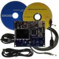
KIT EVAL FOR AT32UC3A0
Manufacturer
Atmel
Series
AVR®32r
Type
MCUr
Datasheets
1.ATAVRONE-PROBECBL.pdf
(16 pages)
2.ATEVK1104.pdf
(826 pages)
3.ATEVK1105.pdf
(28 pages)
Specifications of ATEVK1105
Contents
Evaluation Board, Software and Documentation
Processor To Be Evaluated
AT32UC3A0512
Processor Series
AVR
Data Bus Width
32 bit
Interface Type
USART, TWI, USB, SPI, Ethernet
Operating Supply Voltage
3.3 V
Silicon Manufacturer
Atmel
Core Architecture
AVR
Core Sub-architecture
AVR UC3
Silicon Core Number
AT32UC3A0512
Silicon Family Name
AVR
Kit Contents
Board CD Docs
Rohs Compliant
Yes
For Use With/related Products
AT32UC3A0
Lead Free Status / RoHS Status
Lead free / RoHS Compliant


Shall be cleared by software (by setting the OVERFIC bit) to acknowledge the interrupt.
• STALLEDI: STALLed Interrupt Flag
Set by hardware to signal that a STALL handshake has been sent. To do that, the software has to set the STALLRQ bit (by
setting the STALLRQS bit). This triggers an EPXINT interrupt if STALLEDE = 1.
Shall be cleared by software (by setting the STALLEDIC bit) to acknowledge the interrupt.
• CRCERRI: CRC Error Interrupt Flag
Set by hardware to signal that a CRC error has been detected in an isochronous OUT endpoint. The OUT packet is stored
in the bank as if no CRC error had occurred. This triggers an EPXINT interrupt if CRCERRE = 1.
Shall be cleared by software (by setting the CRCERRIC bit) to acknowledge the interrupt.
• SHORTPACKET: Short Packet Interrupt Flag
For non-control OUT endpoints, set by hardware when a short packet has been received.
For non-control IN endpoints, set by hardware when a short packet is transmitted upon ending a DMA transfer, thus signal-
ing an end of isochronous frame or a bulk or interrupt end of transfer, this only if the End of DMA Buffer Output Enable bit
(DMAEND_EN) and the Automatic Switch bit (AUTOSW) are set.
This triggers an EPXINT interrupt if SHORTPACKETE = 1.
Shall be cleared by software (by setting the SHORTPACKETC bit) to acknowledge the interrupt.
• DTSEQ: Data Toggle Sequence
Set by hardware to indicate the PID of the current bank:
For IN transfers, it indicates the data toggle sequence that will be used for the next packet to be sent. This is not relative to
the current bank.
For OUT transfers, this value indicates the last data toggle sequence received on the current bank.
Note that by default DTSEQ = 01b, as if the last data toggle sequence was Data1, so the next sent or expected data toggle
sequence should be Data0.
• NBUSYBK: Number of Busy Banks
Set by hardware to indicate the number of busy banks:
For IN endpoints, it indicates the number of banks filled by the user and ready for IN transfer. When all banks are free, this
triggers an EPXINT interrupt if NBUSYBKE = 1.
32058J–AVR32–04/11
0
0
1
0
0
1
1
NBUSYBK
DTSEQ
X
0
1
0
1
0
1
Data Toggle Sequence
Data0
Data1
Reserved
Number of Busy Banks
0 (all banks free)
1
2
3
AT32UC3A
575
Related parts for ATEVK1105
Image
Part Number
Description
Manufacturer
Datasheet
Request
R

Part Number:
Description:
DEV KIT FOR AVR/AVR32
Manufacturer:
Atmel
Datasheet:

Part Number:
Description:
INTERVAL AND WIPE/WASH WIPER CONTROL IC WITH DELAY
Manufacturer:
ATMEL Corporation
Datasheet:
Part Number:
Description:
Low-Voltage Voice-Switched IC for Hands-Free Operation
Manufacturer:
ATMEL Corporation
Datasheet:
Part Number:
Description:
MONOLITHIC INTEGRATED FEATUREPHONE CIRCUIT
Manufacturer:
ATMEL Corporation
Datasheet:
Part Number:
Description:
AM-FM Receiver IC U4255BM-M
Manufacturer:
ATMEL Corporation
Datasheet:
Part Number:
Description:
Monolithic Integrated Feature Phone Circuit
Manufacturer:
ATMEL Corporation
Datasheet:
Part Number:
Description:
Multistandard Video-IF and Quasi Parallel Sound Processing
Manufacturer:
ATMEL Corporation
Datasheet:
Part Number:
Description:
High-performance EE PLD
Manufacturer:
ATMEL Corporation
Datasheet:
Part Number:
Description:
8-bit Flash Microcontroller
Manufacturer:
ATMEL Corporation
Datasheet:
Part Number:
Description:
2-Wire Serial EEPROM
Manufacturer:
ATMEL Corporation
Datasheet: