ATEVK1105 Atmel, ATEVK1105 Datasheet - Page 804
ATEVK1105
Manufacturer Part Number
ATEVK1105
Description
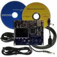
KIT EVAL FOR AT32UC3A0
Manufacturer
Atmel
Series
AVR®32r
Type
MCUr
Datasheets
1.ATAVRONE-PROBECBL.pdf
(16 pages)
2.ATEVK1104.pdf
(826 pages)
3.ATEVK1105.pdf
(28 pages)
Specifications of ATEVK1105
Contents
Evaluation Board, Software and Documentation
Processor To Be Evaluated
AT32UC3A0512
Processor Series
AVR
Data Bus Width
32 bit
Interface Type
USART, TWI, USB, SPI, Ethernet
Operating Supply Voltage
3.3 V
Silicon Manufacturer
Atmel
Core Architecture
AVR
Core Sub-architecture
AVR UC3
Silicon Core Number
AT32UC3A0512
Silicon Family Name
AVR
Kit Contents
Board CD Docs
Rohs Compliant
Yes
For Use With/related Products
AT32UC3A0
Lead Free Status / RoHS Status
Lead free / RoHS Compliant


41.4.4
41.4.5
32058J–AVR32–04/11
Power Manager
FLASHC
4. SPI Bad Serial Clock Generation on 2nd chip_select when SCBR = 1, CPOL=1 and
5. SPI Glitch on RXREADY flag in slave mode when enabling the SPI or during the first
6. SPI Disable does not work in Slave mode
1. Wrong reset causes when BOD is activated
2. If the BOD level is higher than VDDCORE, the part is constantly under reset
1. On AT32UC3A0512 and AT32UC3A1512, corrupted read in flash after FLASHC WP,
NCPHA=0
When multiple CS are in use, if one of the baudrate equals to 1 and one of the others doesn't
equal to 1, and CPOL=1 and CPHA=0, then an aditional pulse will be generated on SCK.
Fix/workaround
When multiple CS are in use, if one of the baudrate equals 1, the other must also equal 1 if
CPOL=1 and CPHA=0.
transfer
In slave mode, the SPI can generate a false RXREADY signal during enabling of the SPI or
during the first transfer.
Fix/Workaround
1. Set slave mode, set required CPOL/CPHA.
2. Enable SPI.
3. Set the polarity CPOL of the line in the opposite value of the required one.
4. Set the polarity CPOL to the required one.
5. Read the RXHOLDING register.
Transfers can now befin and RXREADY will now behave as expected.
Fix/workaround
Read the last received data then perform a Software reset.
Setting the BOD enable fuse will cause the Reset Cause Register to list BOD reset as the
reset source even though the part was reset by another source.
Fix/Workaround
Do not set the BOD enable fuse, but activate the BOD as soon as your program starts.
If the BOD level is set to a value higher than VDDCORE and enabled by fuses, the part will
be in constant reset.
Fix/Workaround
Apply an external voltage on VDDCORE that is higher than the BOD level and is lower than
VDDCORE max and disable the BOD.
EP, EA, WUP, EUP commands may happen
- After a FLASHC Write Page (WP) or Erase Page (EP) command applied to a page in a
given half of the flash (first or last 256 kB of flash), reading (data read or code fetch) the
other half of the flash may fail. This may lead to an exception or to other errors derived from
this corrupted read access.
- After a FLASHC Erase All (EA) command, reading (data read or code fetch) the flash may
fail. This may lead to an exception or to other errors derived from this corrupted read access.
- After a FLASHC Write User Page (WUP) or Erase User Page (EUP) command, reading
804
Related parts for ATEVK1105
Image
Part Number
Description
Manufacturer
Datasheet
Request
R

Part Number:
Description:
DEV KIT FOR AVR/AVR32
Manufacturer:
Atmel
Datasheet:

Part Number:
Description:
INTERVAL AND WIPE/WASH WIPER CONTROL IC WITH DELAY
Manufacturer:
ATMEL Corporation
Datasheet:
Part Number:
Description:
Low-Voltage Voice-Switched IC for Hands-Free Operation
Manufacturer:
ATMEL Corporation
Datasheet:
Part Number:
Description:
MONOLITHIC INTEGRATED FEATUREPHONE CIRCUIT
Manufacturer:
ATMEL Corporation
Datasheet:
Part Number:
Description:
AM-FM Receiver IC U4255BM-M
Manufacturer:
ATMEL Corporation
Datasheet:
Part Number:
Description:
Monolithic Integrated Feature Phone Circuit
Manufacturer:
ATMEL Corporation
Datasheet:
Part Number:
Description:
Multistandard Video-IF and Quasi Parallel Sound Processing
Manufacturer:
ATMEL Corporation
Datasheet:
Part Number:
Description:
High-performance EE PLD
Manufacturer:
ATMEL Corporation
Datasheet:
Part Number:
Description:
8-bit Flash Microcontroller
Manufacturer:
ATMEL Corporation
Datasheet:
Part Number:
Description:
2-Wire Serial EEPROM
Manufacturer:
ATMEL Corporation
Datasheet: