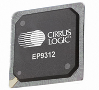
EP9312-CB Cirrus Logic Inc, EP9312-CB Datasheet - Page 748

EP9312-CB
Manufacturer Part Number
EP9312-CB
Description
System-on-Chip Processor
Manufacturer
Cirrus Logic Inc
Series
EP9r
Datasheets
1.EP9307-CRZ.pdf
(824 pages)
2.EP9312-IBZ.pdf
(4 pages)
3.EP9312-CB.pdf
(62 pages)
4.EP9312-CB.pdf
(17 pages)
Specifications of EP9312-CB
Peak Reflow Compatible (260 C)
No
A/d Converter
12 Bits
Leaded Process Compatible
No
No. Of I/o Pins
65
Package / Case
352-BGA
Core Processor
ARM9
Core Size
16/32-Bit
Speed
200MHz
Connectivity
EBI/EMI, EIDE, Ethernet, I²C, IrDA, Keypad/Touchscreen, SPI, UART/USART, USB
Peripherals
AC'97, DMA, I²:S, LCD, LED, MaverickKey, POR, PWM, WDT
Number Of I /o
16
Program Memory Type
ROMless
Ram Size
32K x 8
Voltage - Supply (vcc/vdd)
1.65 V ~ 3.6 V
Data Converters
A/D 8x12b
Oscillator Type
External
Operating Temperature
0°C ~ 70°C
Processor Series
EP93xx
Core
ARM920T
Data Bus Width
32 bit
3rd Party Development Tools
MDK-ARM, RL-ARM, ULINK2
Lead Free Status / RoHS Status
Contains lead / RoHS non-compliant
Eeprom Size
-
Program Memory Size
-
Lead Free Status / Rohs Status
No
Other names
598-1257
Available stocks
Company
Part Number
Manufacturer
Quantity
Price
Part Number:
EP9312-CB
Manufacturer:
CIRRUS
Quantity:
20 000
- EP9307-CRZ PDF datasheet
- EP9312-IBZ PDF datasheet #2
- EP9312-CB PDF datasheet #3
- EP9312-CB PDF datasheet #4
- Current page: 748 of 824
- Download datasheet (13Mb)
25
25-10
Analog Touch Screen Interface
EP93xx User’s Guide
25.2.2 Five-wire and Seven-wire Operation
The algorithm then would continue by discharging and detecting a valid touch. With no X
interrupt pending flag, the algorithm also continues by discharging and detecting a valid
touch, but without interrupt generation. If the difference between the new Y value and the last
Y value is greater than the YMIN value, the algorithm continues by comparing the difference
between the new Y value and the last Y value to the YMAX value in the TSXYMaxMin
register. If the difference is greater than YMAX, it is assumed that this distance is too far for a
touch input to possibly move in the short scan time interval and that the key press is invalid.
However, it is stored as the last recorded Y location in case a truly new location is being
determined (that is, no contact to contact or contact to no contact).
The Y move interrupt pending flag is also set at this point to cause the algorithm to skip over
the comparison to YMIN on consecutive sample sets. This flag will also cause an ARM Core
interrupt as soon as a valid Y sample can be established. The algorithm then starts over
discharging and detecting a valid press. If the difference between the new Y value and the
last stored Y value is less than the YMAX value, the algorithm stores the new Y value in the Y
last register, and the stored X value is moved to the X last register. The interrupt to the ARM
Core is generated, and the algorithm continues by moving to the settle state and detecting a
valid press. The interrupt is cleared when the TSXYResult register is read or by clearing the
TSSetup2.TINT bit.
As can be seen from
8-wire touch screens, except that the reference for the A / D converter is internal instead of a
feedback. The register values TSDetect, TSDischarge, TSXSample, and TSYSample are
derived from the switch positions in the diagram. They are documented in
Five-wire touch screens require a different connection scheme than 4- or 8-wire touch
screens. The X+ and X- lines become static V+ and V- lines. The Y+ and Y- lines are Z+/- and
Z-/+ and are used to switch between X and Y axis. The reference for the A / D converter is
internal. One of the feedback lines, for example, sY+ is used as a Wiper input to the A / D
converter. The register values TSDetect, TSDischarge, TSXSample, and TSYSample are
derived from the switch positions in the diagram. They are provided in
Seven-wire touch screens (5-wires with feedback) are very similar to a normal 5-wire touch
screen, except that the A / D reference is taken from the external circuit. The X+ and X- lines
are still static V+ and V-lines. The Y+ and Y- lines are still Z+/- and Z-/+ and are used to
switch between X and Y axis. However, the reference for the A / D converter is on the sX+
and sX- lines relabelled as sV+ and sV-. The sY+ feedback line is still used as a Wiper input
to the A / D converter.
The register values TSDischarge, TSXSample, and TSYSample are derived from the switch
positions in the diagram. They are provided in
Figure
25-3, 4-wire touch screens are operated in much the same way a
Copyright 2007 Cirrus Logic
Table
25-2.
Table
Table
25-2.
25-2.
DS785UM1
Related parts for EP9312-CB
Image
Part Number
Description
Manufacturer
Datasheet
Request
R

Part Number:
Description:
IC ARM920T MCU 200MHZ 352-PBGA
Manufacturer:
Cirrus Logic Inc
Datasheet:

Part Number:
Description:
IC ARM9 SOC UNIVERSAL 352PBGA
Manufacturer:
Cirrus Logic Inc
Datasheet:

Part Number:
Description:
IC ARM920T MCU 200MHZ 352-PBGA
Manufacturer:
Cirrus Logic Inc
Datasheet:

Part Number:
Description:
IC Universal Platform ARM9 SOC Prcessor
Manufacturer:
Cirrus Logic Inc
Datasheet:

Part Number:
Description:
IC Universal Platform ARM9 SOC Prcessor
Manufacturer:
Cirrus Logic Inc
Datasheet:

Part Number:
Description:
Development Kit
Manufacturer:
Cirrus Logic Inc
Datasheet:

Part Number:
Description:
Development Kit
Manufacturer:
Cirrus Logic Inc
Datasheet:

Part Number:
Description:
High-efficiency PFC + Fluorescent Lamp Driver Reference Design
Manufacturer:
Cirrus Logic Inc
Datasheet:

Part Number:
Description:
Development Kit
Manufacturer:
Cirrus Logic Inc
Datasheet:

Part Number:
Description:
Development Kit
Manufacturer:
Cirrus Logic Inc
Datasheet:

Part Number:
Description:
Development Kit
Manufacturer:
Cirrus Logic Inc
Datasheet:

Part Number:
Description:
Development Kit
Manufacturer:
Cirrus Logic Inc
Datasheet:

Part Number:
Description:
Ref Bd For Speakerbar MSA & DSP Products
Manufacturer:
Cirrus Logic Inc


