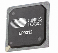
EP9312-CB Cirrus Logic Inc, EP9312-CB Datasheet - Page 134

EP9312-CB
Manufacturer Part Number
EP9312-CB
Description
System-on-Chip Processor
Manufacturer
Cirrus Logic Inc
Series
EP9r
Datasheets
1.EP9307-CRZ.pdf
(824 pages)
2.EP9312-IBZ.pdf
(4 pages)
3.EP9312-CB.pdf
(62 pages)
4.EP9312-CB.pdf
(17 pages)
Specifications of EP9312-CB
Peak Reflow Compatible (260 C)
No
A/d Converter
12 Bits
Leaded Process Compatible
No
No. Of I/o Pins
65
Package / Case
352-BGA
Core Processor
ARM9
Core Size
16/32-Bit
Speed
200MHz
Connectivity
EBI/EMI, EIDE, Ethernet, I²C, IrDA, Keypad/Touchscreen, SPI, UART/USART, USB
Peripherals
AC'97, DMA, I²:S, LCD, LED, MaverickKey, POR, PWM, WDT
Number Of I /o
16
Program Memory Type
ROMless
Ram Size
32K x 8
Voltage - Supply (vcc/vdd)
1.65 V ~ 3.6 V
Data Converters
A/D 8x12b
Oscillator Type
External
Operating Temperature
0°C ~ 70°C
Processor Series
EP93xx
Core
ARM920T
Data Bus Width
32 bit
3rd Party Development Tools
MDK-ARM, RL-ARM, ULINK2
Lead Free Status / RoHS Status
Contains lead / RoHS non-compliant
Eeprom Size
-
Program Memory Size
-
Lead Free Status / Rohs Status
No
Other names
598-1257
Available stocks
Company
Part Number
Manufacturer
Quantity
Price
Part Number:
EP9312-CB
Manufacturer:
CIRRUS
Quantity:
20 000
- EP9307-CRZ PDF datasheet
- EP9312-IBZ PDF datasheet #2
- EP9312-CB PDF datasheet #3
- EP9312-CB PDF datasheet #4
- Current page: 134 of 824
- Download datasheet (13Mb)
5
5-8
5.1.5.2.2
System Controller
EP93xx User’s Guide
Even though FCLK is the usual CPU clock, HCLK can optionally be used instead. Processor
clocking modes are:
Both Async mode and Sync mode use FCLK. FCLK can be faster than HCLK, which would
yield higher performance. Async mode and Sync mode have different clock skew
requirements between FCLK and HCLK, and therefor have different throughput penalties due
to clock synchronization. Fast Bus mode bypasses FCLK, and the CPU runs from HCLK. In
this mode, the ARM Core potentially has lower performance than with the other two modes.
When the ARM Core starts up, it defaults to Fast Bus mode. (The selection of clocking
modes is determined by the iA and nF bits in ARM co-processor 15 register 1.)
The MCLK, VCLK, and MIR_CLK generators are three identical blocks. Each block contains
a pre-divider of 2, 2.5 and 3 followed by a 7-bit programmer divider. The audio clock SCLK
and LRCLK are further divided down from MCLK. The registers,
“VidClkDiv” on page
USB uses a 48 MHz clock generated by PLL2. USBDIV, in register
used to divide the frequency down from the PLL2 output.
The Key Matrix and Touchscreen Controller clocks are generated from an external 14.7 MHz
oscillator. A chain of dividers generates divide-by-2, 4, 8, 16, 32, 64 versions of external
oscillator clock. Programmable bits in the
by-4 or a divide-by-16 version of the external oscillator clock for each of the Key Matrix clock
and Touchscreen controller.
Table 5-3
• Async mode
• Sync mode
• Fast Bus mode
Peripheral Clock Generation
Watchdog
UART1
UART2
UART3
Block
Timers
PWM
SSP
AAC
describes the speeds and sources for the various clocks.
5-29, and
Clocks Used
508.4689 KHz
14.7456 MHz
14.7456 MHz
7.3728 MHz
7.3728 MHz
2.9491 MHz
1.9939 KHz
983 KHz
256 Hz
Table 5-3. Clock Speeds and Sources
Copyright 2007 Cirrus Logic
“I2SClkDiv” on page
Divided by 2 from 14.7456 MHz external oscillator
Both are derived from 14.7456 MHz external oscillator
From the 14.7456MHz external oscillator
Divided-by-5 from the 14.7456MHz external oscillator
All divided by the 14.7456 MHz external oscillator
Tap from the 32 KHz RTC clock
“KeyTchClkDiv” on page 5-32
5-31, show the details.
Clock Source
“MIRClkDiv” on page
“ClkSet2” on page
select either a divide-
DS785UM1
5-20, is
5-30,
Related parts for EP9312-CB
Image
Part Number
Description
Manufacturer
Datasheet
Request
R

Part Number:
Description:
IC ARM920T MCU 200MHZ 352-PBGA
Manufacturer:
Cirrus Logic Inc
Datasheet:

Part Number:
Description:
IC ARM9 SOC UNIVERSAL 352PBGA
Manufacturer:
Cirrus Logic Inc
Datasheet:

Part Number:
Description:
IC ARM920T MCU 200MHZ 352-PBGA
Manufacturer:
Cirrus Logic Inc
Datasheet:

Part Number:
Description:
IC Universal Platform ARM9 SOC Prcessor
Manufacturer:
Cirrus Logic Inc
Datasheet:

Part Number:
Description:
IC Universal Platform ARM9 SOC Prcessor
Manufacturer:
Cirrus Logic Inc
Datasheet:

Part Number:
Description:
Development Kit
Manufacturer:
Cirrus Logic Inc
Datasheet:

Part Number:
Description:
Development Kit
Manufacturer:
Cirrus Logic Inc
Datasheet:

Part Number:
Description:
High-efficiency PFC + Fluorescent Lamp Driver Reference Design
Manufacturer:
Cirrus Logic Inc
Datasheet:

Part Number:
Description:
Development Kit
Manufacturer:
Cirrus Logic Inc
Datasheet:

Part Number:
Description:
Development Kit
Manufacturer:
Cirrus Logic Inc
Datasheet:

Part Number:
Description:
Development Kit
Manufacturer:
Cirrus Logic Inc
Datasheet:

Part Number:
Description:
Development Kit
Manufacturer:
Cirrus Logic Inc
Datasheet:

Part Number:
Description:
Ref Bd For Speakerbar MSA & DSP Products
Manufacturer:
Cirrus Logic Inc


