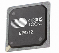
EP9312-CB Cirrus Logic Inc, EP9312-CB Datasheet - Page 296

EP9312-CB
Manufacturer Part Number
EP9312-CB
Description
System-on-Chip Processor
Manufacturer
Cirrus Logic Inc
Series
EP9r
Datasheets
1.EP9307-CRZ.pdf
(824 pages)
2.EP9312-IBZ.pdf
(4 pages)
3.EP9312-CB.pdf
(62 pages)
4.EP9312-CB.pdf
(17 pages)
Specifications of EP9312-CB
Peak Reflow Compatible (260 C)
No
A/d Converter
12 Bits
Leaded Process Compatible
No
No. Of I/o Pins
65
Package / Case
352-BGA
Core Processor
ARM9
Core Size
16/32-Bit
Speed
200MHz
Connectivity
EBI/EMI, EIDE, Ethernet, I²C, IrDA, Keypad/Touchscreen, SPI, UART/USART, USB
Peripherals
AC'97, DMA, I²:S, LCD, LED, MaverickKey, POR, PWM, WDT
Number Of I /o
16
Program Memory Type
ROMless
Ram Size
32K x 8
Voltage - Supply (vcc/vdd)
1.65 V ~ 3.6 V
Data Converters
A/D 8x12b
Oscillator Type
External
Operating Temperature
0°C ~ 70°C
Processor Series
EP93xx
Core
ARM920T
Data Bus Width
32 bit
3rd Party Development Tools
MDK-ARM, RL-ARM, ULINK2
Lead Free Status / RoHS Status
Contains lead / RoHS non-compliant
Eeprom Size
-
Program Memory Size
-
Lead Free Status / Rohs Status
No
Other names
598-1257
Available stocks
Company
Part Number
Manufacturer
Quantity
Price
Part Number:
EP9312-CB
Manufacturer:
CIRRUS
Quantity:
20 000
- EP9307-CRZ PDF datasheet
- EP9312-IBZ PDF datasheet #2
- EP9312-CB PDF datasheet #3
- EP9312-CB PDF datasheet #4
- Current page: 296 of 824
- Download datasheet (13Mb)
8
8-32
Graphics Accelerator
EP93xx User’s Guide
D:
M:
SYDIR, SXDIR:
DYDIR, DXDIR:
Copyright 2007 Cirrus Logic
‘1’ - Pixel Expansion Mapping Function enabled
‘0’ - Pixel Expansion Mapping Function disabled
The Pixel Expansion Mapping Function converts single bit
pixels in the source image to defined pixel-depth (see
Table
When BG = ‘0’, source image pixels are unaffected
(transparent) when they are copied to the destination
image. When BG = ‘1’, source image pixels that have a
value of ‘0’ are copied to the destination image with the
color value in the BG field of the
and source image pixels that have a value of ‘1’ are copied
to the destination image with the color value in the MASK
field of the
Destination Mode - Read/Write
The value in the this field specifies the destination mode:
‘00’ - Disabled
‘01’ - Destination AND Mode
‘10’ - Destination OR Mode
‘11’ - Destination XOR Mode
Mask Mode - Read/Write
The value in the this field specifies the mask mode:
‘00’ - Disabled
‘01’ - Mask AND Mode
‘10’ - Mask OR Mode
‘11’ - Mask XOR Mode
Counter/Accumulator Direction - Read/Write
Write the values of the DYDIR and DXDIR bits to the
SYDIR and DXDIR bits, respectively.
Counter/Accumulator and Line Direction - Read/Write
The value of these bits specifies the general direction that
the current Graphics Acceleration function places pixels
on the display:
For a Block Fill or Block Copy function:
DXDIR = ‘1’ - Left in X
DXDIR = ‘0’ - Right in X
DYDIR = ‘1’ - Up in Y
8-23) pixels in the destination image.
BLOCKMASK
register.
BACKGROUND
DS785UM1
register
Related parts for EP9312-CB
Image
Part Number
Description
Manufacturer
Datasheet
Request
R

Part Number:
Description:
IC ARM920T MCU 200MHZ 352-PBGA
Manufacturer:
Cirrus Logic Inc
Datasheet:

Part Number:
Description:
IC ARM9 SOC UNIVERSAL 352PBGA
Manufacturer:
Cirrus Logic Inc
Datasheet:

Part Number:
Description:
IC ARM920T MCU 200MHZ 352-PBGA
Manufacturer:
Cirrus Logic Inc
Datasheet:

Part Number:
Description:
IC Universal Platform ARM9 SOC Prcessor
Manufacturer:
Cirrus Logic Inc
Datasheet:

Part Number:
Description:
IC Universal Platform ARM9 SOC Prcessor
Manufacturer:
Cirrus Logic Inc
Datasheet:

Part Number:
Description:
Development Kit
Manufacturer:
Cirrus Logic Inc
Datasheet:

Part Number:
Description:
Development Kit
Manufacturer:
Cirrus Logic Inc
Datasheet:

Part Number:
Description:
High-efficiency PFC + Fluorescent Lamp Driver Reference Design
Manufacturer:
Cirrus Logic Inc
Datasheet:

Part Number:
Description:
Development Kit
Manufacturer:
Cirrus Logic Inc
Datasheet:

Part Number:
Description:
Development Kit
Manufacturer:
Cirrus Logic Inc
Datasheet:

Part Number:
Description:
Development Kit
Manufacturer:
Cirrus Logic Inc
Datasheet:

Part Number:
Description:
Development Kit
Manufacturer:
Cirrus Logic Inc
Datasheet:

Part Number:
Description:
Ref Bd For Speakerbar MSA & DSP Products
Manufacturer:
Cirrus Logic Inc


