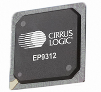
EP9312-CB Cirrus Logic Inc, EP9312-CB Datasheet - Page 140

EP9312-CB
Manufacturer Part Number
EP9312-CB
Description
System-on-Chip Processor
Manufacturer
Cirrus Logic Inc
Series
EP9r
Datasheets
1.EP9307-CRZ.pdf
(824 pages)
2.EP9312-IBZ.pdf
(4 pages)
3.EP9312-CB.pdf
(62 pages)
4.EP9312-CB.pdf
(17 pages)
Specifications of EP9312-CB
Peak Reflow Compatible (260 C)
No
A/d Converter
12 Bits
Leaded Process Compatible
No
No. Of I/o Pins
65
Package / Case
352-BGA
Core Processor
ARM9
Core Size
16/32-Bit
Speed
200MHz
Connectivity
EBI/EMI, EIDE, Ethernet, I²C, IrDA, Keypad/Touchscreen, SPI, UART/USART, USB
Peripherals
AC'97, DMA, I²:S, LCD, LED, MaverickKey, POR, PWM, WDT
Number Of I /o
16
Program Memory Type
ROMless
Ram Size
32K x 8
Voltage - Supply (vcc/vdd)
1.65 V ~ 3.6 V
Data Converters
A/D 8x12b
Oscillator Type
External
Operating Temperature
0°C ~ 70°C
Processor Series
EP93xx
Core
ARM920T
Data Bus Width
32 bit
3rd Party Development Tools
MDK-ARM, RL-ARM, ULINK2
Lead Free Status / RoHS Status
Contains lead / RoHS non-compliant
Eeprom Size
-
Program Memory Size
-
Lead Free Status / Rohs Status
No
Other names
598-1257
Available stocks
Company
Part Number
Manufacturer
Quantity
Price
Part Number:
EP9312-CB
Manufacturer:
CIRRUS
Quantity:
20 000
- EP9307-CRZ PDF datasheet
- EP9312-IBZ PDF datasheet #2
- EP9312-CB PDF datasheet #3
- EP9312-CB PDF datasheet #4
- Current page: 140 of 824
- Download datasheet (13Mb)
5
Register Descriptions
PwrSts
5-14
System Controller
EP93xx User’s Guide
WDTFLG
31
15
Address:
Definition:
Bit Descriptions:
RSVD
30
14
CLDFLG
29
13
RESET
TEST_
28
12
0x8093_0000 - Read Only
The PwrSts system control register is the Power/State control register.
RSVD:
RTCDIV:
PLL1_LOCK:
PLL1_LOCK_REG:Registered PLL1 lock. This is a one-shot registered signal
PLL2_LOCK:
PLL2_LOCK_REG:Registered PLL2 lock. This is a one-shot registered signal
SW_RESET:
CHIPMAN
RSTFLG
27
11
RESET
SW_
26
10
Copyright 2007 Cirrus Logic
LOCK_REG
PLL2_
25
9
Reserved. Unknown During Read.
The 6-bit RTCDIV shows the number of 64-seconds which
have elapsed. It is the output of the divide-by-64 chain that
divides the 64 Hz TICK clock down to 1 Hz though
showing an incrementing count. The MSB is the 1 Hz
output; the LSB is the 32 Hz output. It is reset by power-
on-reset to 000000b.
PLL1 lock. This signal goes high when PLL1 is locked and
it is at the correct frequency.
of the PLL1_LOCK signal. It is only cleared on a power-
on-reset, when the device enters the Standby state or
when PLL1 is powered down.
PLL2 lock. This signal goes high when PLL2 is locked, and
it is at the correct frequency.
of the PLL2_LOCK signal. It is only cleared on a power-
on-reset, when ClkSet2 is written, the device enters the
Standby state, or PLL2 is powered down.
Software reset flag. This bit is set if the software reset has
been activated. It is cleared by writing to the STFClr
location. On power-on-reset, it is reset to 0b.
PLL2_
LOCK
24
8
LOCK_REG
PLL1_
23
7
PLL1_
LOCK
22
6
21
5
CHIPID
20
4
19
3
RTCDIV
18
2
DS785UM1
17
1
16
0
Related parts for EP9312-CB
Image
Part Number
Description
Manufacturer
Datasheet
Request
R

Part Number:
Description:
IC ARM920T MCU 200MHZ 352-PBGA
Manufacturer:
Cirrus Logic Inc
Datasheet:

Part Number:
Description:
IC ARM9 SOC UNIVERSAL 352PBGA
Manufacturer:
Cirrus Logic Inc
Datasheet:

Part Number:
Description:
IC ARM920T MCU 200MHZ 352-PBGA
Manufacturer:
Cirrus Logic Inc
Datasheet:

Part Number:
Description:
IC Universal Platform ARM9 SOC Prcessor
Manufacturer:
Cirrus Logic Inc
Datasheet:

Part Number:
Description:
IC Universal Platform ARM9 SOC Prcessor
Manufacturer:
Cirrus Logic Inc
Datasheet:

Part Number:
Description:
Development Kit
Manufacturer:
Cirrus Logic Inc
Datasheet:

Part Number:
Description:
Development Kit
Manufacturer:
Cirrus Logic Inc
Datasheet:

Part Number:
Description:
High-efficiency PFC + Fluorescent Lamp Driver Reference Design
Manufacturer:
Cirrus Logic Inc
Datasheet:

Part Number:
Description:
Development Kit
Manufacturer:
Cirrus Logic Inc
Datasheet:

Part Number:
Description:
Development Kit
Manufacturer:
Cirrus Logic Inc
Datasheet:

Part Number:
Description:
Development Kit
Manufacturer:
Cirrus Logic Inc
Datasheet:

Part Number:
Description:
Development Kit
Manufacturer:
Cirrus Logic Inc
Datasheet:

Part Number:
Description:
Ref Bd For Speakerbar MSA & DSP Products
Manufacturer:
Cirrus Logic Inc


