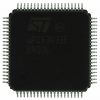
UPSD3433EB40U6 STMicroelectronics, UPSD3433EB40U6 Datasheet - Page 48

UPSD3433EB40U6
Manufacturer Part Number
UPSD3433EB40U6
Description
MCU 8BIT 8032 128KB FLASH 80TQFP
Manufacturer
STMicroelectronics
Series
µPSDr
Datasheet
1.UPSD3434EB40T6.pdf
(293 pages)
Specifications of UPSD3433EB40U6
Core Processor
8032
Core Size
8-Bit
Speed
40MHz
Connectivity
I²C, IrDA, SPI, UART/USART, USB
Peripherals
LVD, POR, PWM, WDT
Number Of I /o
46
Program Memory Size
160KB (160K x 8)
Program Memory Type
FLASH
Ram Size
8K x 8
Voltage - Supply (vcc/vdd)
3 V ~ 5.5 V
Data Converters
A/D 8x10b
Oscillator Type
Internal
Operating Temperature
-40°C ~ 85°C
Package / Case
80-TQFP, 80-VQFP
For Use With
497-5518 - EVAL BOARD RFID READER497-5046 - KIT TOOL FOR ST7/UPSD/STR7 MCU
Lead Free Status / RoHS Status
Lead free / RoHS Compliant
Eeprom Size
-
Other names
497-5660
Available stocks
Company
Part Number
Manufacturer
Quantity
Price
Company:
Part Number:
UPSD3433EB40U6
Manufacturer:
STMicroelectronics
Quantity:
10 000
- Current page: 48 of 293
- Download datasheet (5Mb)
Dual data pointers
11.2
11.2.1
48/293
Data pointer mode register, DPTM (86h)
The two “background” data pointers, DPTR0 and DPTR1, can be configured to
automatically increment, decrement, or stay the same after a MOVX instruction accesses
the DPTR Register. Only the currently selected pointer will be affected by the increment or
decrement. This feature is controlled by the DPTM Register defined in
The automatic increment or decrement function is effective only for the MOVX instruction,
and not MOVC or any other instruction that uses the DTPR Register.
Firmware example
The 8051 assembly code illustrated in
from one XDATA address region to another XDATA address region. Auto-address
incrementing and auto-pointer toggling will be used.
Table 14.
Table 15.
Bit 7
7-4
3-2
1-0
Bit
–
MOV
MOV
MOV
MOV
MOV
MOV
MD[11:10]
MD[01:00]
DPTM: data pointer mode register (SFR 86h, reset value 00h)
8051 assembly code example
Symbol
Bit 6
–
–
R7, #COUNT
DPTR,
#SOURCE_ADDR
85h, #01h
DPTR, #DEST_ADDR ; load XDATA destination address base into DPTR1
85h, #40h
86h, #0Ah
Bit 5
R/W
R,W
R,W
–
–
DPTR1 Mode Bits
00: DPTR1 No Change
01: Reserved
10: Auto Increment
11: Auto Decrement
DPTR0 Mode Bits
00: DPTR0 No Change
01: Reserved
10: Auto Increment
11: Auto Decrement
Bit 4
Table 15
–
; initialize size of data block to transfer
; load XDATA source address base into DPTR0
; load DPTC to access DPTR1 pointer
; load DPTC to access DPTR0 pointer and auto
toggle
; load DPTM to auto-increment both pointers
shows how to transfer a block of data bytes
MD11
Bit 3
Definition
Reserved
MD10
Bit 2
Table
MD01
Bit 1
14.
uPSD34xx
MD00
Bit 0
Related parts for UPSD3433EB40U6
Image
Part Number
Description
Manufacturer
Datasheet
Request
R

Part Number:
Description:
MCU 8BIT 8032 128KB FLASH 80TQFP
Manufacturer:
STMicroelectronics
Datasheet:

Part Number:
Description:
MCU 8BIT 8032 128KB FLASH 52TQFP
Manufacturer:
STMicroelectronics
Datasheet:

Part Number:
Description:
STMicroelectronics [RIPPLE-CARRY BINARY COUNTER/DIVIDERS]
Manufacturer:
STMicroelectronics
Datasheet:

Part Number:
Description:
STMicroelectronics [LIQUID-CRYSTAL DISPLAY DRIVERS]
Manufacturer:
STMicroelectronics
Datasheet:

Part Number:
Description:
BOARD EVAL FOR MEMS SENSORS
Manufacturer:
STMicroelectronics
Datasheet:

Part Number:
Description:
NPN TRANSISTOR POWER MODULE
Manufacturer:
STMicroelectronics
Datasheet:

Part Number:
Description:
TURBOSWITCH ULTRA-FAST HIGH VOLTAGE DIODE
Manufacturer:
STMicroelectronics
Datasheet:

Part Number:
Description:
Manufacturer:
STMicroelectronics
Datasheet:

Part Number:
Description:
DIODE / SCR MODULE
Manufacturer:
STMicroelectronics
Datasheet:

Part Number:
Description:
DIODE / SCR MODULE
Manufacturer:
STMicroelectronics
Datasheet:

Part Number:
Description:
Search -----> STE16N100
Manufacturer:
STMicroelectronics
Datasheet:

Part Number:
Description:
Search ---> STE53NA50
Manufacturer:
STMicroelectronics
Datasheet:


