STEVAL-MKI062V2 STMicroelectronics, STEVAL-MKI062V2 Datasheet
STEVAL-MKI062V2
Specifications of STEVAL-MKI062V2
Available stocks


Related parts for STEVAL-MKI062V2


STEVAL-MKI062V2 Summary of contents
Page 1
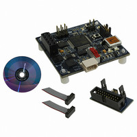
... Getting started with the STEVAL-MKI032V1, STM32-MEMS 1 Introduction This user manual describes the STEVAL-MKI032V1, STM32-MEMS demonstration board which serves as interface between the STM32™ demonstration board (STMicroelectronics™ STM3210B-EVAL, STM3210E-EVAL, IAR KickStart Kit™ for STM32) and the MEMS demonstration board (any STEVAL-MKI0xxVx compatible with DIL24 socket). ...
Page 2
Contents Contents 1 Introduction . . . . . . . . . . . . . . . . . . . . . . . . . . . . . . . . . . . . ...
Page 3
UM0701 7.1 MEMS Library . . . . . . . . . . . . . . . . . . . . . . . . . . . . . . . . . . . . ...
Page 4
List of tables List of tables Table 1. Connecting the STM32-MEMS board to the STM3210B-EVAL board . . . . . . . . . . . . . . . . . 9 Table 2. Analog MEMS signals connected ...
Page 5
... UM0701 List of figures Figure 1. STEVAL-MKI032V1, STM32-MEMS demonstration board, top view . . . . . . . . . . . . . . . . . . 1 Figure 2. System with STM32-MEMS demonstration board . . . . . . . . . . . . . . . . . . . . . . . . . . . . . . . . 7 Figure 3. STM32-MEMS demonstration board layout . . . . . . . . . . . . . . . . . . . . . . . . . . . . . . . . . . . . . 8 Figure 4. Connecting MEMS demonstration board to STM32-MEMS board . . . . . . . . . . . . . . . . . . . . 9 Figure 5. STM3210B-EVAL board with STM32-MEMS board connected . . . . . . . . . . . . . . . . . . . . . 10 Figure 6. Setup for analog MEMS . . . . . . . . . . . . . . . . . . . . . . . . . . . . . . . . . . . . . . . . . . . . . . . . . . . 10 Figure 7. ...
Page 6
... IAR KickStart Kit™ for STM32 (STM3210B-SK/IAR) - full-featured demonstration board with STM32F103B microcontroller, standalone J-Link debugger/programmer, IAR Embedded Workbench development environment, IAR C/C++ compiler. ● Compatible with all STEVAL-MKI0xxVx MEMS accelerometer demonstration boards suitable for DIL24 sockets. Recommended boards are: – digital MEMS accelerometers: STEVAL-MKI013V1 (LIS302DL), STEVAL- MKI009V1 (LIS3LV02DL), – ...
Page 7
... STM32 MCU), STM3210E-EVAL board (with high-density STM32 MCU) and STM3210B-SK/IAR (for medium-density STM32 MCU). The STM32-MEMS board has a DIL24 socket to connect any STEVAL-MKI0xxVx MEMS demonstration board compatible with the socket. The recommended boards are: digital MEMS accelerometers STEVAL-MKI013V1 (LIS302DL) and STEVAL-MKI009V1 (LIS3LV02DL), and analog MEMS accelerometers STEVAL-MKI015V1 (LIS344ALH), STEVAL-MKI018V1 (LIS244AL) and STEVAL-MKI020V1 (LIS302SG) ...
Page 8
Board layout 4 Board layout Figure 3. STM32-MEMS demonstration board layout 8/42 Doc ID 15703 Rev 1 UM0701 ...
Page 9
UM0701 5 System setup The system consists of three boards: the STM32 demonstration board, the STM32-MEMS demonstration board and the MEMS demonstration board. The set-up of the system can be split into three main steps. 1. Set-up of the STM32 ...
Page 10
System setup Figure 5. STM3210B-EVAL board with STM32-MEMS board connected 5.1.2 Setup for analog MEMS Position the JP1, JP2 and JP3 jumpers on the STM32-MEMS board. No modification is needed on the STM3210B-EVAL board. Figure 6. Setup for analog MEMS ...
Page 11
UM0701 The CN13-4-pin of the STM3210B-EVAL is also used by the Tamper button. The Tamper button cannot be used when using the Int2 signal. Figure 7. Setup for digital MEMS - SPI interface 5.1.4 Setup for digital MEMS - I ...
Page 12
System setup 5.1.5 Analog MEMS signals connected to STM32 pins Table 2. Analog MEMS signals connected to STM32 pins Analog MEMS signal 5.1.6 Digital MEMS signals connected to STM32 pins Table 3. System setup with STM3210E-EVAL board Common signals SPI ...
Page 13
UM0701 Figure 9. STM3210E-EVAL board with STM32-MEMS board connected 5.2.2 Setup for analog MEMS Position the JP5, JP13 and JP14 jumpers on the STM32-MEMS board. No modification is needed on the STM3210E-EVAL board. Figure 10. Setup for analog MEMS 5.2.3 ...
Page 14
System setup Figure 11. Setup for digital MEMS - SPI interface 5.2.4 Setup for digital MEMS - I Position the JP5, JP8, JP9 and JP11 jumpers on the STM32-MEMS board. Remove R32 from the STM3210E-EVAL board. If Int1 signal is ...
Page 15
UM0701 5.2.5 Analog MEMS signals connected to STM32 pins Table 5. Analog MEMS signals connected to STM32 pins Analog MEMS signal 5.2.6 Digital MEMS signals connected to STM32 pins Table 6. Digital MEMS signals connected to STM32 pins Digital MEMS ...
Page 16
System setup Table 7. Connecting the STM32-MEMS board to the STM3210B-SK/IAR board Pin of STM32-MEMS board Figure 14. STM3210B-SK/IAR board with STM32-MEMS board connected 5.3.2 Setup for all MEMS Position the JP4 and JP5 jumpers on the STM32-MEMS board. To ...
Page 17
UM0701 5.3.3 Analog MEMS signals connected to STM32 pins Table 8. Analog MEMS signals connected to STM32 pins Analog MEMS signal 5.3.4 Digital MEMS signals connected to STM32 pins Table 9. Digital MEMS signals connected to STM32 pins Common signals ...
Page 18
Remote connection option 6 Remote connection option The remote connection option can be used when the MEMS sensor needs to be placed in a position where the STM32 demonstration board does not fit, for example for motor vibration measurement applications. ...
Page 19
UM0701 Table 10. CN7 connector pinout Pin 6.2 Analog axis selection - JP15 jumper This jumper is used to select which analog axis is connected to the CN8 BNC connector. ...
Page 20
... MEMS Library This section describes the firmware interface (called MEMS Library) used to manage the MEMS sensor attached to the STEVAL-MKI032V1, STM32-MEMS demonstration board by the STM32 microcontroller. The main purpose of this firmware library is to provide resources to ease the development of applications using a MEMS sensor. The MEMS Library is designed to be used with the STM32-MEMS demonstration board ...
Page 21
UM0701 stm32_mems.h This file provides constants containing the I value related to several digital MEMS sensors (LIS302DL, LIS3LV02DL). It also defines a type used to store data from the axis of a MEMS accelerometer. stm32_mems_adapter.h This file provides constants for ...
Page 22
STM32-MEMS development kit Table 12. MEMS Library functions Function name MEMS_SPI_WriteReg MEMS_SPI_ReadReg MEMS_SPI_SendFrame MEMS_SPI_ReceiveFrame MEMS_I2C_Setup MEMS_I2C_Set_Address MEMS_I2C_WriteReg MEMS_I2C_ReadReg MEMS_I2C_SendFrame MEMS_I2C_ReceiveFrame 7.2.1 MEMS_ANL_Setup function Table 13 describes the MEMS_ANL_Setup function. Table 13. MEMS_ANL_Setup function Function name Function prototype Description Input parameter ...
Page 23
UM0701 7.2.3 MEMS_ANL_Drive_PD function Table 15 describes the MEMS_ANL_Drive_PD function. Table 15. MEMS_ANL_Drive_PD function Function name Function prototype Description Input parameter Output parameter Return parameter 7.2.4 MEMS_ANL_ADC_Restart function Table 16 describes the MEMS_ANL_ADC_Restart function. Table 16. MEMS_ANL_ADC_Restart function Function name ...
Page 24
STM32-MEMS development kit 7.2.6 MEMS_DIG_Setup_Int1 function Table 18 describes the MEMS_DIG_Setup_Int1 function. Table 18. MEMS_DIG_Setup_Int1 function Function name Function prototype Description Input parameter Output parameter Return parameter 7.2.7 MEMS_DIG_Setup_Int2 function Table 19 describes the MEMS_DIG_Setup_Int2 function. Table 19. MEMS_DIG_Setup_Int2 function ...
Page 25
UM0701 7.2.9 MEMS_SPI_WriteReg function Table 21 describes the MEMS_SPI_WriteReg function. Table 21. MEMS_SPI_WriteReg function Function name Function prototype Description Input parameter1 Input parameter2 Output parameter Return parameter 7.2.10 MEMS_SPI_ReadReg function Table 22 describes the MEMS_SPI_ReadReg function. Table 22. MEMS_SPI_ReadReg function ...
Page 26
STM32-MEMS development kit 7.2.11 MEMS_SPI_SendFrame function Table 23 describes the MEMS_SPI_SendFrame function. Table 23. MEMS_SPI_SendFrame function Function name Function prototype Description Input parameter1 Input parameter2 Input parameter3 Output parameter Return parameter 7.2.12 MEMS_SPI_ReceiveFrame function Table 24 describes the MEMS_SPI_ReceiveFrame function. ...
Page 27
UM0701 7.2.13 MEMS_I2C_Setup function Table 25 describes the MEMS_I2C_Setup function. . Table 25. MEMS_I2C_Setup function Function name Function prototype Description Input parameter Output parameter Return parameter 7.2.14 MEMS_I2C_Set_Address function Table 26 describes the MEMS_I2C_Set_Address function. Table 26. MEMS_I2C_Set_Address function Function ...
Page 28
STM32-MEMS development kit 7.2.16 MEMS_I2C_ReadReg function Table 28 describes the MEMS_I2C_ReadReg function. Table 28. MEMS_I2C_ReadReg function Function name Function prototype Description Input parameter Output parameter Return parameter 7.2.17 MEMS_I2C_SendFrame function Table 29 describes the MEMS_I2C_SendFrame function. Table 29. MEMS_I2C_SendFrame function ...
Page 29
UM0701 7.2.18 MEMS_I2C_ReceiveFrame function Table 30 describes the MEMS_I2C_ReceiveFrame function. Table 30. MEMS_I2C_ReceiveFrame function Function name Function prototype Description Input parameter1 Input parameter2 Output parameter Return parameter STM32-MEMS development kit MEMS_I2C_ReceiveFrame ErrorStatus MEMS_I2C_ReceiveFrame (u8 RegAddress, u8 *pBuffer, u8 NoOfBytes) 2 ...
Page 30
STM32-MEMS development kit 7.3 Example of MEMS Library usage: analog MEMS This section shows an example of a main function to set-up and read data from an analog MEMS. Do not forget to set-up the defines in the stm32_mems_adapter.h file ...
Page 31
UM0701 7.4 Example of MEMS Library usage: digital MEMS over I This section shows an example of the main function to set-up and read data from a digital 2 MEMS over the I SPI) would make this example work over ...
Page 32
... STM32-MEMS LCD demonstration application (STM32_MEMS_LCD_IAR) for the STM3210B_SK_IAR board. All demonstration applications are designed and tested to be used with the STEVAL-MKI032V1, STM32-MEMS demonstration board as a bridge between the STM32 demonstration board and the MEMS demonstration board. These demonstration applications have been tested with the following MEMS demonstration boards. ● ...
Page 33
UM0701 7.5.1 STM32-MEMS USB demonstration application The STM32-MEMS USB demonstration application reads data from the MEMS sensor and sends it over USB to a PC. On the PC side runs the MEMS USB Reader (Windows GUI application), which use an ...
Page 34
STM32-MEMS development kit Figure 19. MEMS USB Reader Windows GUI application 7.5.2 STM32-MEMS LCD demonstration applications The STM32-MEMS LCD demonstration applications read data from the MEMS sensor and display it on the LCD mounted on the STM32 demonstration board. When ...
Page 35
UM0701 Figure 20. STM32-MEMS LCD demonstration application running on STM3210B_EVAL (left) and STM3210B_SK_IAR (right) 7.6 Application tips: inclination measurement In this application, the acceleration is used to measure an inclination. This inclination is related to the angle achieved by the ...
Page 36
STM32-MEMS development kit Figure 22. Inclination measurement In this example, the device has an The y axis is not affected and the acceleration measured will remain equal to 0. However, for the x axis, the acceleration measured will move from ...
Page 37
UM0701 7.6.2 Chip selection Depending on the type of architecture, the user has to select either an analog or digital MEMS device. After, depending on the precision needed, the user will choose either the LIS344ALH or LIS3LV02DL, if small-angle detection ...
Page 38
Bill of materials Appendix A Bill of materials Table 31. Bill of material Designator CN8 JP1, JP2, JP3, JP4, JP5, JP6, JP7, JP8, JP9, JP10, JP11, JP12, JP13, JP14 JP16 CN4 JP15 CN7 CN1, CN2 CN5, CN6 CN3 R1 38/42 ...
Page 39
UM0701 Appendix B Artwork prints This section shows the layout of the STM32-MEMS demonstration board PCB. Figure 24. STM32-MEMS demonstration board PCB (top and bottom layers) Doc ID 15703 Rev 1 Artwork prints 39/42 ...
Page 40
Board schematic Appendix C Board schematic Figure 25. Board schematic 40/42 Doc ID 15703 Rev 1 UM0701 ...
Page 41
UM0701 Revision history Table 32. Document revision history Date 01-Jul-2009 Revision 1 Initial release. Doc ID 15703 Rev 1 Revision history Changes 41/42 ...
Page 42
... Information in this document is provided solely in connection with ST products. STMicroelectronics NV and its subsidiaries (“ST”) reserve the right to make changes, corrections, modifications or improvements, to this document, and the products and services described herein at any time, without notice. All ST products are sold pursuant to ST’s terms and conditions of sale. ...