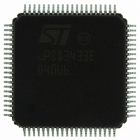
UPSD3433EB40U6 STMicroelectronics, UPSD3433EB40U6 Datasheet - Page 125

UPSD3433EB40U6
Manufacturer Part Number
UPSD3433EB40U6
Description
MCU 8BIT 8032 128KB FLASH 80TQFP
Manufacturer
STMicroelectronics
Series
µPSDr
Datasheet
1.UPSD3434EB40T6.pdf
(293 pages)
Specifications of UPSD3433EB40U6
Core Processor
8032
Core Size
8-Bit
Speed
40MHz
Connectivity
I²C, IrDA, SPI, UART/USART, USB
Peripherals
LVD, POR, PWM, WDT
Number Of I /o
46
Program Memory Size
160KB (160K x 8)
Program Memory Type
FLASH
Ram Size
8K x 8
Voltage - Supply (vcc/vdd)
3 V ~ 5.5 V
Data Converters
A/D 8x10b
Oscillator Type
Internal
Operating Temperature
-40°C ~ 85°C
Package / Case
80-TQFP, 80-VQFP
For Use With
497-5518 - EVAL BOARD RFID READER497-5046 - KIT TOOL FOR ST7/UPSD/STR7 MCU
Lead Free Status / RoHS Status
Lead free / RoHS Compliant
Eeprom Size
-
Other names
497-5660
Available stocks
Company
Part Number
Manufacturer
Quantity
Price
Company:
Part Number:
UPSD3433EB40U6
Manufacturer:
STMicroelectronics
Quantity:
10 000
- Current page: 125 of 293
- Download datasheet (5Mb)
uPSD34xx
23.12
Note:
1
I
The S1SETUP register
will be sampled before the SIOE validates the START condition, giving the SIOE the ability
to reject noise or illegal transmissions.
Because the minimum duration of an START condition varies with I
also because the uPSD34xx may be operated with a wide variety of frequencies (f
necessary to scale the number of samples per START condition based on f
In Slave mode, the SIOE recognizes the beginning of a START condition when it detects a
'1'-to-'0' transition on the SDA bus line while the SCL line is high (see
page
ensure SDA remains low and SCL remains high for a minimum amount of hold time,
t
condition.
If the EN_SS Bit (in the S1SETUP Register) is not set, then the SIOE will sample only once
after detecting the '1'-to-'0' transition on SDA. This single sample is taken 1/f
after the initial 1-to-0 transition was detected. However, more samples should be taken to
ensure there is a valid START condition.
To take more samples, the SIOE should be initialized such that the EN_SS Bit is set, and a
value is written to the SMPL_SET[6:0] field of the S1SETUP Register to specify how many
samples to take. The goal is to take a good number of samples during the minimum START
condition hold time, t
t
Table 60 on page 126
resulting number of I
on SDA of a START condition.
Important note: Keep in mind that the time between samples is always 1/f
The minimum START condition hold time, t
speed categories per
Table 59.
Sampling SCL and SDA lines begins after '1'-to-'0' transition on SDA occurred while SCL is
high. Time between samples is 1/f
HLDSTA
HLDSTA
2
C START sample setting (S1SETUP)
EN_SS
Bit 7
Bit
6:0
7
117). The SIOE must then validate the START condition by sampling the bus lines to
. Once validated, the SIOE begins receiving the address byte that follows the START
expires.
SMPL_SET
S1SETUP: I
value 00h)
Symbol
EN_SS
Bit 6
[6:0]
2
HLDSTA
C bus samples that SIOE will take after detecting the 1-to-0 transition
Table 61 on page
describes the relationship between the contents of S1SETUP and the
(Table
2
C START condition sample setup register (SFR DBh, reset
Bit 5
R/W
R/W
, but no so many samples that the bus will be sampled after
–
59) determines how many times an I
OSC
Enable Sample Setup
EN_SS = 1 will force the SIOE to sample
on the bus the number of times specified in SMPL_SET[6:0].
EN_SS = 0 means the SIOE will sample
only one time, regardless of the contents of SMPL_SET[6:0].
Sample Setting
Specifies the number of bus samples
condition. See
Bit 4
.
126.
HLDSTA
SMPL_SET[6:0]
Table 60
Bit 3
, is different for the three common I
for values.
Function
Bit 2
2
2
C bus speed (f
C bus START condition
(1)
Figure 42 on
taken during a START
(1)
(1)
Bit 1
OSC
a START condition
a START condition
OSC
OSC
.
I
2
and f
C interface
seconds
SCL
OSC
Bit 0
125/293
SCL
2
), and
), it is
C
.
Related parts for UPSD3433EB40U6
Image
Part Number
Description
Manufacturer
Datasheet
Request
R

Part Number:
Description:
MCU 8BIT 8032 128KB FLASH 80TQFP
Manufacturer:
STMicroelectronics
Datasheet:

Part Number:
Description:
MCU 8BIT 8032 128KB FLASH 52TQFP
Manufacturer:
STMicroelectronics
Datasheet:

Part Number:
Description:
STMicroelectronics [RIPPLE-CARRY BINARY COUNTER/DIVIDERS]
Manufacturer:
STMicroelectronics
Datasheet:

Part Number:
Description:
STMicroelectronics [LIQUID-CRYSTAL DISPLAY DRIVERS]
Manufacturer:
STMicroelectronics
Datasheet:

Part Number:
Description:
BOARD EVAL FOR MEMS SENSORS
Manufacturer:
STMicroelectronics
Datasheet:

Part Number:
Description:
NPN TRANSISTOR POWER MODULE
Manufacturer:
STMicroelectronics
Datasheet:

Part Number:
Description:
TURBOSWITCH ULTRA-FAST HIGH VOLTAGE DIODE
Manufacturer:
STMicroelectronics
Datasheet:

Part Number:
Description:
Manufacturer:
STMicroelectronics
Datasheet:

Part Number:
Description:
DIODE / SCR MODULE
Manufacturer:
STMicroelectronics
Datasheet:

Part Number:
Description:
DIODE / SCR MODULE
Manufacturer:
STMicroelectronics
Datasheet:

Part Number:
Description:
Search -----> STE16N100
Manufacturer:
STMicroelectronics
Datasheet:

Part Number:
Description:
Search ---> STE53NA50
Manufacturer:
STMicroelectronics
Datasheet:


