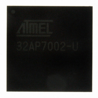
AT32AP7002-CTUT Atmel, AT32AP7002-CTUT Datasheet - Page 252

AT32AP7002-CTUT
Manufacturer Part Number
AT32AP7002-CTUT
Description
IC MCU 32BIT AVR32 196-CBGA
Manufacturer
Atmel
Series
AVR®32 AP7r
Specifications of AT32AP7002-CTUT
Core Processor
AVR
Core Size
32-Bit
Speed
150MHz
Connectivity
EBI/EMI, I²C, MMC, PS2, SPI, SSC, UART/USART, USB
Peripherals
AC'97, DMA, I²C, LCD, POR, PWM, WDT
Number Of I /o
85
Program Memory Type
ROMless
Ram Size
32K x 8
Voltage - Supply (vcc/vdd)
1.65 V ~ 1.95 V
Data Converters
D/A 2x16b
Oscillator Type
Internal
Operating Temperature
-40°C ~ 85°C
Package / Case
196-CBGA
Data Bus Width
32 bit
Data Ram Size
32 KB
Interface Type
I2C, JTAG, PS2, SPI, SSC, UART, USART, USB
Maximum Clock Frequency
150 MHz
Number Of Timers
3
Maximum Operating Temperature
+ 85 C
Mounting Style
SMD/SMT
Minimum Operating Temperature
- 40 C
On-chip Dac
16 bit, 2 Channel
Package
196CTBGA
Device Core
AVR32
Family Name
AT32
Maximum Speed
150 MHz
Operating Supply Voltage
1.8|3.3 V
For Use With
ATAVRONEKIT - KIT AVR/AVR32 DEBUGGER/PROGRMMRATNGW100 - KIT AVR32 NETWORK GATEWAYATSTK1000 - KIT STARTER FOR AVR32AP7000
Lead Free Status / RoHS Status
Lead free / RoHS Compliant
Eeprom Size
-
Program Memory Size
-
Lead Free Status / Rohs Status
Details
Available stocks
Company
Part Number
Manufacturer
Quantity
Price
- Current page: 252 of 896
- Download datasheet (13Mb)
Figure 19-6. Input Change Interrupt Timings
19.6
32054F–AVR32–09/09
Read ISR
CLK_PIO
Pin Level
ISR
I/O Lines Programming Example
When an input change is detected on an I/O line, the corresponding bit in ISR (Interrupt Status
Register) is set. If the corresponding bit in IMR is set, the PIO Controller interrupt line is
asserted. The interrupt signals of the thirty-two channels are ORed-wired together to generate a
single interrupt signal to the Interrupt Controller.
When the software reads ISR, all the interrupts are automatically cleared. This signifies that all
the interrupts that are pending when ISR is read must be handled.
The programing example as shown in
configuration.
•4-bit output port on I/O lines 0 to 3, (should be written in a single write operation)
•Four output signals on I/O lines 4 to 7 (to drive LEDs for example)
•Four input signals on I/O lines 8 to 11 (to read push-button states for example), with pull-up
•Four input signals on I/O line 12 to 15 to read an external device status (polled, thus no input
•I/O lines 16 to 19 assigned to peripheral A functions with pull-up resistor
•I/O lines 20 to 23 assigned to peripheral B functions, no pull-up resistor
•I/O line 24 to 27 assigned to peripheral A with Input Change Interrupt and pull-up resistor
resistors, glitch filters and input change interrupts
change interrupt), no pull-up resistor, no glitch filter
Peripheral Bus Access
Table 19-1
below is used to define the following
Peripheral Bus Access
AT32AP7002
252
Related parts for AT32AP7002-CTUT
Image
Part Number
Description
Manufacturer
Datasheet
Request
R

Part Number:
Description:
DEV KIT FOR AVR/AVR32
Manufacturer:
Atmel
Datasheet:

Part Number:
Description:
INTERVAL AND WIPE/WASH WIPER CONTROL IC WITH DELAY
Manufacturer:
ATMEL Corporation
Datasheet:

Part Number:
Description:
Low-Voltage Voice-Switched IC for Hands-Free Operation
Manufacturer:
ATMEL Corporation
Datasheet:

Part Number:
Description:
MONOLITHIC INTEGRATED FEATUREPHONE CIRCUIT
Manufacturer:
ATMEL Corporation
Datasheet:

Part Number:
Description:
AM-FM Receiver IC U4255BM-M
Manufacturer:
ATMEL Corporation
Datasheet:

Part Number:
Description:
Monolithic Integrated Feature Phone Circuit
Manufacturer:
ATMEL Corporation
Datasheet:

Part Number:
Description:
Multistandard Video-IF and Quasi Parallel Sound Processing
Manufacturer:
ATMEL Corporation
Datasheet:

Part Number:
Description:
High-performance EE PLD
Manufacturer:
ATMEL Corporation
Datasheet:

Part Number:
Description:
8-bit Flash Microcontroller
Manufacturer:
ATMEL Corporation
Datasheet:

Part Number:
Description:
2-Wire Serial EEPROM
Manufacturer:
ATMEL Corporation
Datasheet:


