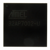
AT32AP7002-CTUT Atmel, AT32AP7002-CTUT Datasheet - Page 102

AT32AP7002-CTUT
Manufacturer Part Number
AT32AP7002-CTUT
Description
IC MCU 32BIT AVR32 196-CBGA
Manufacturer
Atmel
Series
AVR®32 AP7r
Specifications of AT32AP7002-CTUT
Core Processor
AVR
Core Size
32-Bit
Speed
150MHz
Connectivity
EBI/EMI, I²C, MMC, PS2, SPI, SSC, UART/USART, USB
Peripherals
AC'97, DMA, I²C, LCD, POR, PWM, WDT
Number Of I /o
85
Program Memory Type
ROMless
Ram Size
32K x 8
Voltage - Supply (vcc/vdd)
1.65 V ~ 1.95 V
Data Converters
D/A 2x16b
Oscillator Type
Internal
Operating Temperature
-40°C ~ 85°C
Package / Case
196-CBGA
Data Bus Width
32 bit
Data Ram Size
32 KB
Interface Type
I2C, JTAG, PS2, SPI, SSC, UART, USART, USB
Maximum Clock Frequency
150 MHz
Number Of Timers
3
Maximum Operating Temperature
+ 85 C
Mounting Style
SMD/SMT
Minimum Operating Temperature
- 40 C
On-chip Dac
16 bit, 2 Channel
Package
196CTBGA
Device Core
AVR32
Family Name
AT32
Maximum Speed
150 MHz
Operating Supply Voltage
1.8|3.3 V
For Use With
ATAVRONEKIT - KIT AVR/AVR32 DEBUGGER/PROGRMMRATNGW100 - KIT AVR32 NETWORK GATEWAYATSTK1000 - KIT STARTER FOR AVR32AP7000
Lead Free Status / RoHS Status
Lead free / RoHS Compliant
Eeprom Size
-
Program Memory Size
-
Lead Free Status / Rohs Status
Details
Available stocks
Company
Part Number
Manufacturer
Quantity
Price
- Current page: 102 of 896
- Download datasheet (13Mb)
10.5.6.2
10.5.6.3
32054F–AVR32–09/09
Supported sleep modes
Precautions when entering sleep mode
The following sleep modes are supported. These are detailed in
•Idle: The CPU is stopped, the rest of the chip is operating. Wake-up sources are any interrupt,
or WAKE_N pin.
•Frozen: The CPU and HSB modules are stopped, peripherals are operating. Wake-up sources
are any interrupt from PB modules, or WAKE_N pin.
•Standby: All synchronous clocks are stopped, but oscillators and PLL’s are running, allowing
quick wake-up to normal mode. Wake-up sources are RTC or external interrupt, or WAKE_N
pin.
•Stop: As Standby, but Oscillator 0 and 1, and the PLL’s are stopped. 32 KHz oscillator and
RTC/WDT still operates. Wake-up sources are RTC or external interrupt, or WAKE_N pin.
•Static: All oscillators and clocks are stopped. Wake-up sources are external interrupt or
WAKE_N pin.•
Table 10-2.
Modules communicating with external circuits should normally be disabled before entering a
sleep mode that will stop the module operation. This prevents erratic behavior when entering or
exiting sleep mode. Please refer to the relevant module documentation for recommended
actions.
Communication between the synchronous clock domains is disturbed when entering and exiting
sleep modes. This means that bus transactions are not allowed between clock domains affected
by the sleep mode. The system may hang if the bus clocks are stopped in the middle of a bus
transaction.
The CPU and caches are automatically stopped in a safe state to ensure that all CPU bus oper-
ations are complete when the sleep mode goes into effect. Thus, when entering Idle mode, no
further action is necessary.
When entering a deeper sleep mode than Idle mode, all other HSB masters must be stopped
before entering the sleep mode. Also, if there is a chance that any PB write operations are
incomplete, the CPU should perform a read operation from any register on the PB bus before
executing the sleep instruction. This will stall the CPU while waiting for any pending PB opera-
tions to complete.
The Power manager will normally turn of all debug related clocks in the system in the static sleep
mode, making it impossible for a debugger to communicate with the system. If a
Index
0
1
2
3
5
Sleep Mode
Idle
Frozen
Standby
Stop
Static
Sleep modes
CPU
Off
Off
Off
Off
Off
HSB
On
Off
Off
Off
Off
PBA,B +
GCLK
On
On
Off
Off
Off
Table
On
Osc0,1 +
PLL0,1
On
On
Off
Off
10-2.
AT32AP7002
Osc32 +
RTC/WDT
On
On
On
On
Off
102
Related parts for AT32AP7002-CTUT
Image
Part Number
Description
Manufacturer
Datasheet
Request
R

Part Number:
Description:
DEV KIT FOR AVR/AVR32
Manufacturer:
Atmel
Datasheet:

Part Number:
Description:
INTERVAL AND WIPE/WASH WIPER CONTROL IC WITH DELAY
Manufacturer:
ATMEL Corporation
Datasheet:

Part Number:
Description:
Low-Voltage Voice-Switched IC for Hands-Free Operation
Manufacturer:
ATMEL Corporation
Datasheet:

Part Number:
Description:
MONOLITHIC INTEGRATED FEATUREPHONE CIRCUIT
Manufacturer:
ATMEL Corporation
Datasheet:

Part Number:
Description:
AM-FM Receiver IC U4255BM-M
Manufacturer:
ATMEL Corporation
Datasheet:

Part Number:
Description:
Monolithic Integrated Feature Phone Circuit
Manufacturer:
ATMEL Corporation
Datasheet:

Part Number:
Description:
Multistandard Video-IF and Quasi Parallel Sound Processing
Manufacturer:
ATMEL Corporation
Datasheet:

Part Number:
Description:
High-performance EE PLD
Manufacturer:
ATMEL Corporation
Datasheet:

Part Number:
Description:
8-bit Flash Microcontroller
Manufacturer:
ATMEL Corporation
Datasheet:

Part Number:
Description:
2-Wire Serial EEPROM
Manufacturer:
ATMEL Corporation
Datasheet:


