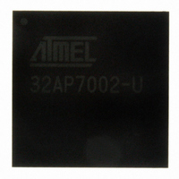
AT32AP7002-CTUT Atmel, AT32AP7002-CTUT Datasheet - Page 129

AT32AP7002-CTUT
Manufacturer Part Number
AT32AP7002-CTUT
Description
IC MCU 32BIT AVR32 196-CBGA
Manufacturer
Atmel
Series
AVR®32 AP7r
Specifications of AT32AP7002-CTUT
Core Processor
AVR
Core Size
32-Bit
Speed
150MHz
Connectivity
EBI/EMI, I²C, MMC, PS2, SPI, SSC, UART/USART, USB
Peripherals
AC'97, DMA, I²C, LCD, POR, PWM, WDT
Number Of I /o
85
Program Memory Type
ROMless
Ram Size
32K x 8
Voltage - Supply (vcc/vdd)
1.65 V ~ 1.95 V
Data Converters
D/A 2x16b
Oscillator Type
Internal
Operating Temperature
-40°C ~ 85°C
Package / Case
196-CBGA
Data Bus Width
32 bit
Data Ram Size
32 KB
Interface Type
I2C, JTAG, PS2, SPI, SSC, UART, USART, USB
Maximum Clock Frequency
150 MHz
Number Of Timers
3
Maximum Operating Temperature
+ 85 C
Mounting Style
SMD/SMT
Minimum Operating Temperature
- 40 C
On-chip Dac
16 bit, 2 Channel
Package
196CTBGA
Device Core
AVR32
Family Name
AT32
Maximum Speed
150 MHz
Operating Supply Voltage
1.8|3.3 V
For Use With
ATAVRONEKIT - KIT AVR/AVR32 DEBUGGER/PROGRMMRATNGW100 - KIT AVR32 NETWORK GATEWAYATSTK1000 - KIT STARTER FOR AVR32AP7000
Lead Free Status / RoHS Status
Lead free / RoHS Compliant
Eeprom Size
-
Program Memory Size
-
Lead Free Status / Rohs Status
Details
Available stocks
Company
Part Number
Manufacturer
Quantity
Price
- Current page: 129 of 896
- Download datasheet (13Mb)
13.4
13.4.1
13.4.2
13.4.3
13.5
32054F–AVR32–09/09
Product Dependencies
Functional Description
Power Management
Clocks
Debug Operation
Figure 13-1. INTC Block Diagram
In order to use this module, other parts of the system must be configured correctly, as described
below.
If the CPU enters a sleep mode that disables clocks used by the INTC, the INTC will stop func-
tioning and resume operation after the system wakes up from sleep mode.
The clock for the INTC bus interface (CLK_INTC) is generated by the Power Manager. This
clock is enabled at reset, and can be disabled in the Power Manager.
When an external debugger forces the CPU into debug mode, the INTC continues normal
operation.
All of the incoming interrupt requests (IREQs) are sampled into the corresponding Interrupt
Request Register (IRR). The IRRs must be accessed to identify which IREQ within a group that
is active. If several IREQs within the same group are active, the interrupt service routine must
prioritize between them. All of the input lines in each group are logically ORed together to form
the GrpReqN lines, indicating if there is a pending interrupt in the corresponding group.
The Request Masking hardware maps each of the GrpReq lines to a priority level from INT0 to
INT3 by associating each group with the Interrupt Level (INTLEVEL) field in the corresponding
Interrupt Priority Register (IPR). The GrpReq inputs are then masked by the mask bits from the
CPU status register. Any interrupt group that has a pending interrupt of a priority level that is not
masked by the CPU status register, gets its corresponding ValReq line asserted.
NMIREQ
IREQ63
IREQ34
IREQ33
IREQ32
IREQ31
IREQ2
IREQ1
IREQ0
IRR Registers
Interrupt Controller
OR
OR
OR
IRRn
IRR1
IRR0
GrpReq1
GrpReq0
GrpReqN
.
.
.
Request
Masking
ValReqN
ValReq1
ValReq0
IPRn
IPR1
IPR0
.
.
.
IPR Registers
INT_level,
INT_level,
INT_level,
offset
offset
offset
.
.
.
ICR Registers
AT32AP7002
AUTOVECTOR
INTLEVEL
Masks
CPU
I[3-0]M
SREG
Masks
GM
129
Related parts for AT32AP7002-CTUT
Image
Part Number
Description
Manufacturer
Datasheet
Request
R

Part Number:
Description:
DEV KIT FOR AVR/AVR32
Manufacturer:
Atmel
Datasheet:

Part Number:
Description:
INTERVAL AND WIPE/WASH WIPER CONTROL IC WITH DELAY
Manufacturer:
ATMEL Corporation
Datasheet:

Part Number:
Description:
Low-Voltage Voice-Switched IC for Hands-Free Operation
Manufacturer:
ATMEL Corporation
Datasheet:

Part Number:
Description:
MONOLITHIC INTEGRATED FEATUREPHONE CIRCUIT
Manufacturer:
ATMEL Corporation
Datasheet:

Part Number:
Description:
AM-FM Receiver IC U4255BM-M
Manufacturer:
ATMEL Corporation
Datasheet:

Part Number:
Description:
Monolithic Integrated Feature Phone Circuit
Manufacturer:
ATMEL Corporation
Datasheet:

Part Number:
Description:
Multistandard Video-IF and Quasi Parallel Sound Processing
Manufacturer:
ATMEL Corporation
Datasheet:

Part Number:
Description:
High-performance EE PLD
Manufacturer:
ATMEL Corporation
Datasheet:

Part Number:
Description:
8-bit Flash Microcontroller
Manufacturer:
ATMEL Corporation
Datasheet:

Part Number:
Description:
2-Wire Serial EEPROM
Manufacturer:
ATMEL Corporation
Datasheet:


