AT91SAM9G45-EKES Atmel, AT91SAM9G45-EKES Datasheet - Page 984
AT91SAM9G45-EKES
Manufacturer Part Number
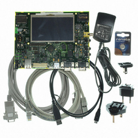
AT91SAM9G45-EKES
Description
KIT EVAL FOR AT91SAM9G45
Manufacturer
Atmel
Series
AT91SAM Smart ARMr
Type
MCUr
Datasheets
1.AT91SAM9G45-EKES.pdf
(56 pages)
2.AT91SAM9G45-EKES.pdf
(1218 pages)
3.AT91SAM9G45-EKES.pdf
(66 pages)
Specifications of AT91SAM9G45-EKES
Contents
Board
Processor To Be Evaluated
SAM9G45
Data Bus Width
32 bit
Interface Type
I2C, SPI, UART
Maximum Operating Temperature
+ 50 C
Minimum Operating Temperature
- 10 C
Operating Supply Voltage
1.8 V to 3.3 V
For Use With/related Products
AT91SAM9G45
Lead Free Status / RoHS Status
Lead free / RoHS Compliant
Other names
Q4626953


41.4.5
41.4.5.1
41.4.5.2
6438F–ATARM–21-Jun-10
Programming a Channel
Programming Examples
Single-buffer Transfer (Row 1)
Four registers, the DMAC_DSCRx, the DMAC_CTRLAx, the DMAC_CTRLBx and
DMAC_CFGx, need to be programmed to set up whether single or multi-buffer transfers take
place, and which type of multi-buffer transfer is used. The different transfer types are shown in
Table 41-2 on page
The “BTSIZE, SADDR and DADDR” columns indicate where the values of DMAC_SARx,
DMAC_DARx, DMAC_CTLx, and DMAC_LLPx are obtained for the next buffer transfer when
multi-buffer DMAC transfers are enabled.
1. Read the Channel Handler Status Register DMAC_CHSR.ENABLE Field to choose a
2. Clear any pending interrupts on the channel from the previous DMAC transfer by read-
3. Program the following channel registers:
free (disabled) channel.
ing the interrupt status register, DMAC_EBCISR.
a. Write the starting source address in the DMAC_SADDRx register for channel x.
b. Write the starting destination address in the DMAC_DADDRx register for channel
c. Program DMAC_CTRLAx, DMAC_CTRLBx and DMAC_CFGx according to Row 1
d. Write the control information for the DMAC transfer in the DMAC_CTRLAx and
– i. Set up the transfer type (memory or non-memory peripheral for source and
– ii. Set up the transfer characteristics, such as:
e. Write the channel configuration information into the DMAC_CFGx register for chan-
– i. Designate the handshaking interface type (hardware or software) for the source
destination) and flow control device by programming the FC of the DMAC_CTRLBx
register.
and destination peripherals. This is not required for memory. This step requires
programming the SRC_H2SEL/DST_H2SEL bits, respectively. Writing a ‘1’ activates
the hardware handshaking interface to handle source/destination requests. Writing a
‘0’ activates the software handshaking interface to handle source/destination
requests.
– Transfer width for the source in the SRC_WIDTH field.
– Transfer width for the destination in the DST_WIDTH field.
– Source AHB Master interface layer in the SIF field where source resides.
– Destination AHB Master Interface layer in the DIF field where destination resides.
– Incrementing/decrementing or fixed address for source in SRC_INC field.
– Incrementing/decrementing or fixed address for destination in DST_INC field.
x.
as shown in
both DST_DSCR and SRC_DSCR fields set to one and AUTO field set to 0.
DMAC_CTRLBx registers for channel x. For example, in the register, you can pro-
gram the following:
nel x.
982.
Table 41-2 on page
982. Program the DMAC_CTRLBx register with
AT91SAM9G45
984
Related parts for AT91SAM9G45-EKES
Image
Part Number
Description
Manufacturer
Datasheet
Request
R

Part Number:
Description:
MCU ARM9 64K SRAM 144-LFBGA
Manufacturer:
Atmel
Datasheet:

Part Number:
Description:
IC ARM7 MCU FLASH 256K 100LQFP
Manufacturer:
Atmel
Datasheet:

Part Number:
Description:
IC ARM9 MPU 217-LFBGA
Manufacturer:
Atmel
Datasheet:
Part Number:
Description:
MCU ARM9 ULTRA LOW PWR 217-LFBGA
Manufacturer:
Atmel
Datasheet:

Part Number:
Description:
MCU ARM9 324-TFBGA
Manufacturer:
Atmel
Datasheet:
Part Number:
Description:
IC MCU ARM9 SAMPLING 217CBGA
Manufacturer:
Atmel
Datasheet:
Part Number:
Description:
IC ARM9 MCU 217-LFBGA
Manufacturer:
Atmel
Datasheet:

Part Number:
Description:
IC ARM9 MCU 208-PQFP
Manufacturer:
Atmel
Datasheet:
Part Number:
Description:
MCU ARM 512K HS FLASH 100-LQFP
Manufacturer:
Atmel
Datasheet:

Part Number:
Description:
MCU ARM 512K HS FLASH 100-TFBGA
Manufacturer:
Atmel
Datasheet:
Part Number:
Description:
IC ARM9 MCU 200 MHZ 324-TFBGA
Manufacturer:
Atmel
Datasheet:

Part Number:
Description:
IC ARM MCU 16BIT 128K 256BGA
Manufacturer:
Atmel
Datasheet:

Part Number:
Description:
IC ARM7 MCU 32BIT 128K 64LQFP
Manufacturer:
Atmel
Datasheet:

Part Number:
Description:
IC ARM7 MCU FLASH 256K 128-LQFP
Manufacturer:
Atmel
Datasheet:
Part Number:
Description:
IC ARM7 MCU FLASH 512K 128-LQFP
Manufacturer:
Atmel
Datasheet: