AT91SAM9G45-EKES Atmel, AT91SAM9G45-EKES Datasheet - Page 361
AT91SAM9G45-EKES
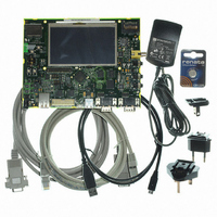
Manufacturer Part Number
AT91SAM9G45-EKES
Description
KIT EVAL FOR AT91SAM9G45
Manufacturer
Atmel
Series
AT91SAM Smart ARMr
Type
MCUr
Datasheets
1.AT91SAM9G45-EKES.pdf
(56 pages)
2.AT91SAM9G45-EKES.pdf
(1218 pages)
3.AT91SAM9G45-EKES.pdf
(66 pages)
Specifications of AT91SAM9G45-EKES
Contents
Board
Processor To Be Evaluated
SAM9G45
Data Bus Width
32 bit
Interface Type
I2C, SPI, UART
Maximum Operating Temperature
+ 50 C
Minimum Operating Temperature
- 10 C
Operating Supply Voltage
1.8 V to 3.3 V
For Use With/related Products
AT91SAM9G45
Lead Free Status / RoHS Status
Lead free / RoHS Compliant
Other names
Q4626953


Figure 27-10. Character Transmission
27.5.3.3
Figure 27-11. Transmitter Control
27.5.4
6438F–ATARM–21-Jun-10
Shift Register
DBGU_THR
TXEMPTY
TXRDY
DTXD
Peripheral Data Controller
in DBGU_THR
Write Data 0
Transmitter Control
Baud Rate
Example: Parity enabled
DTXD
Clock
S
Data 0
in DBGU_THR
PARE in the mode register DBGU_MR defines whether or not a parity bit is shifted out. When a
parity bit is enabled, it can be selected between an odd parity, an even parity, or a fixed space or
mark bit.
When the transmitter is enabled, the bit TXRDY (Transmitter Ready) is set in the status register
DBGU_SR. The transmission starts when the programmer writes in the Transmit Holding Regis-
ter DBGU_THR, and after the written character is transferred from DBGU_THR to the Shift
Register. The bit TXRDY remains high until a second character is written in DBGU_THR. As
soon as the first character is completed, the last character written in DBGU_THR is transferred
into the shift register and TXRDY rises again, showing that the holding register is empty.
When both the Shift Register and the DBGU_THR are empty, i.e., all the characters written in
DBGU_THR have been processed, the bit TXEMPTY rises after the last stop bit has been
completed.
Both the receiver and the transmitter of the Debug Unit's UART are generally connected to a
Peripheral Data Controller (PDC) channel.
The peripheral data controller channels are programmed via registers that are mapped within
the Debug Unit user interface from the offset 0x100. The status bits are reported in the Debug
Unit status register DBGU_SR and can generate an interrupt.
Write Data 1
Start
Bit
Data 0
D0
Data 0
D1
P
D2
stop
D3
S
D4
D5
Data 1
D6
Data 1
D7
Parity
Bit
AT91SAM9G45
P
Stop
Bit
Data 1
stop
361
Related parts for AT91SAM9G45-EKES
Image
Part Number
Description
Manufacturer
Datasheet
Request
R

Part Number:
Description:
MCU ARM9 64K SRAM 144-LFBGA
Manufacturer:
Atmel
Datasheet:

Part Number:
Description:
IC ARM7 MCU FLASH 256K 100LQFP
Manufacturer:
Atmel
Datasheet:

Part Number:
Description:
IC ARM9 MPU 217-LFBGA
Manufacturer:
Atmel
Datasheet:
Part Number:
Description:
MCU ARM9 ULTRA LOW PWR 217-LFBGA
Manufacturer:
Atmel
Datasheet:

Part Number:
Description:
MCU ARM9 324-TFBGA
Manufacturer:
Atmel
Datasheet:
Part Number:
Description:
IC MCU ARM9 SAMPLING 217CBGA
Manufacturer:
Atmel
Datasheet:
Part Number:
Description:
IC ARM9 MCU 217-LFBGA
Manufacturer:
Atmel
Datasheet:

Part Number:
Description:
IC ARM9 MCU 208-PQFP
Manufacturer:
Atmel
Datasheet:
Part Number:
Description:
MCU ARM 512K HS FLASH 100-LQFP
Manufacturer:
Atmel
Datasheet:

Part Number:
Description:
MCU ARM 512K HS FLASH 100-TFBGA
Manufacturer:
Atmel
Datasheet:
Part Number:
Description:
IC ARM9 MCU 200 MHZ 324-TFBGA
Manufacturer:
Atmel
Datasheet:

Part Number:
Description:
IC ARM MCU 16BIT 128K 256BGA
Manufacturer:
Atmel
Datasheet:

Part Number:
Description:
IC ARM7 MCU 32BIT 128K 64LQFP
Manufacturer:
Atmel
Datasheet:

Part Number:
Description:
IC ARM7 MCU FLASH 256K 128-LQFP
Manufacturer:
Atmel
Datasheet:
Part Number:
Description:
IC ARM7 MCU FLASH 512K 128-LQFP
Manufacturer:
Atmel
Datasheet: