AT91SAM9G45-EKES Atmel, AT91SAM9G45-EKES Datasheet - Page 1031
AT91SAM9G45-EKES
Manufacturer Part Number
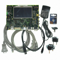
AT91SAM9G45-EKES
Description
KIT EVAL FOR AT91SAM9G45
Manufacturer
Atmel
Series
AT91SAM Smart ARMr
Type
MCUr
Datasheets
1.AT91SAM9G45-EKES.pdf
(56 pages)
2.AT91SAM9G45-EKES.pdf
(1218 pages)
3.AT91SAM9G45-EKES.pdf
(66 pages)
Specifications of AT91SAM9G45-EKES
Contents
Board
Processor To Be Evaluated
SAM9G45
Data Bus Width
32 bit
Interface Type
I2C, SPI, UART
Maximum Operating Temperature
+ 50 C
Minimum Operating Temperature
- 10 C
Operating Supply Voltage
1.8 V to 3.3 V
For Use With/related Products
AT91SAM9G45
Lead Free Status / RoHS Status
Lead free / RoHS Compliant
Other names
Q4626953


42.6.2
42.6.2.1
42.6.2.2
6438F–ATARM–21-Jun-10
PWM Channel
Block Diagram
Waveform Properties
After a reset of the PWM controller, DIVA (DIVB) and PREA (PREB) in the PWM Mode register
are set to 0. This implies that after reset clkA (clkB) are turned off.
At reset, all clocks provided by the modulo n counter are turned off except clock “clk”. This situa-
tion is also true when the PWM master clock is turned off through the Power Management
Controller.
Figure 42-3. Functional View of the Channel Block Diagram
Each of the 4 channels is composed of three blocks:
The different properties of output waveforms are:
• A clock selector which selects one of the clocks provided by the clock generator described in
• An internal counter clocked by the output of the clock selector. This internal counter is
• A comparator used to generate events according to the internal counter value. It also
• the internal clock selection. The internal channel counter is clocked by one of the clocks
• the waveform period. This channel parameter is defined in the CPRD field of the
inputs from
from clock
generator
APB bus
Section 42.6.1 “PWM Clock Generator” on page
incremented or decremented according to the channel configuration and comparators events.
The size of the internal counter is 16 bits.
computes the PWMx output waveform according to the configuration.
provided by the clock generator described in the previous section. This channel parameter is
defined in the CPRE field of the PWM_CMRx register. This field is reset at 0.
PWM_CPRDx register.
- If the waveform is left aligned, then the output waveform period depends on the counter
source clock and can be calculated:
By using the Master Clock (MCK) divided by an X given prescaler value
(with X being 1, 2, 4, 8, 16, 32, 64, 128, 256, 512, or 1024), the resulting period formula
will be:
By using a Master Clock divided by one of both DIVA or DIVB divider, the formula becomes,
respectively:
------------------------------ -
inputs
X CPRD
MCK
Channel
Selector
Clock
Counter
Internal
1030.
Comparator
AT91SAM9G45
PWMx
output waveform
1031
Related parts for AT91SAM9G45-EKES
Image
Part Number
Description
Manufacturer
Datasheet
Request
R

Part Number:
Description:
MCU ARM9 64K SRAM 144-LFBGA
Manufacturer:
Atmel
Datasheet:

Part Number:
Description:
IC ARM7 MCU FLASH 256K 100LQFP
Manufacturer:
Atmel
Datasheet:

Part Number:
Description:
IC ARM9 MPU 217-LFBGA
Manufacturer:
Atmel
Datasheet:
Part Number:
Description:
MCU ARM9 ULTRA LOW PWR 217-LFBGA
Manufacturer:
Atmel
Datasheet:

Part Number:
Description:
MCU ARM9 324-TFBGA
Manufacturer:
Atmel
Datasheet:
Part Number:
Description:
IC MCU ARM9 SAMPLING 217CBGA
Manufacturer:
Atmel
Datasheet:
Part Number:
Description:
IC ARM9 MCU 217-LFBGA
Manufacturer:
Atmel
Datasheet:

Part Number:
Description:
IC ARM9 MCU 208-PQFP
Manufacturer:
Atmel
Datasheet:
Part Number:
Description:
MCU ARM 512K HS FLASH 100-LQFP
Manufacturer:
Atmel
Datasheet:

Part Number:
Description:
MCU ARM 512K HS FLASH 100-TFBGA
Manufacturer:
Atmel
Datasheet:
Part Number:
Description:
IC ARM9 MCU 200 MHZ 324-TFBGA
Manufacturer:
Atmel
Datasheet:

Part Number:
Description:
IC ARM MCU 16BIT 128K 256BGA
Manufacturer:
Atmel
Datasheet:

Part Number:
Description:
IC ARM7 MCU 32BIT 128K 64LQFP
Manufacturer:
Atmel
Datasheet:

Part Number:
Description:
IC ARM7 MCU FLASH 256K 128-LQFP
Manufacturer:
Atmel
Datasheet:
Part Number:
Description:
IC ARM7 MCU FLASH 512K 128-LQFP
Manufacturer:
Atmel
Datasheet: