AT91SAM9G45-EKES Atmel, AT91SAM9G45-EKES Datasheet - Page 587
AT91SAM9G45-EKES
Manufacturer Part Number
AT91SAM9G45-EKES
Description
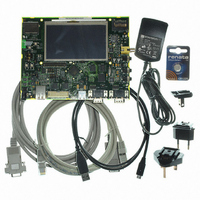
KIT EVAL FOR AT91SAM9G45
Manufacturer
Atmel
Series
AT91SAM Smart ARMr
Type
MCUr
Datasheets
1.AT91SAM9G45-EKES.pdf
(56 pages)
2.AT91SAM9G45-EKES.pdf
(1218 pages)
3.AT91SAM9G45-EKES.pdf
(66 pages)
Specifications of AT91SAM9G45-EKES
Contents
Board
Processor To Be Evaluated
SAM9G45
Data Bus Width
32 bit
Interface Type
I2C, SPI, UART
Maximum Operating Temperature
+ 50 C
Minimum Operating Temperature
- 10 C
Operating Supply Voltage
1.8 V to 3.3 V
For Use With/related Products
AT91SAM9G45
Lead Free Status / RoHS Status
Lead free / RoHS Compliant
Other names
Q4626953


33.7.4
33.7.4.1
Figure 33-30. Connection of a Smart Card to the USART
33.7.4.2
6438F–ATARM–21-Jun-10
ISO7816 Mode
ISO7816 Mode Overview
Protocol T = 0
The USART features an ISO7816-compatible operating mode. This mode permits interfacing
with smart cards and Security Access Modules (SAM) communicating through an ISO7816 link.
Both T = 0 and T = 1 protocols defined by the ISO7816 specification are supported.
Setting the USART in ISO7816 mode is performed by writing the USART_MODE field in the
Mode Register (US_MR) to the value 0x4 for protocol T = 0 and to the value 0x5 for protocol T =
1.
The ISO7816 is a half duplex communication on only one bidirectional line. The baud rate is
determined by a division of the clock provided to the remote device (see
on page
The USART connects to a smart card as shown in
tional and the Baud Rate Generator feeds the ISO7816 clock on the SCK pin. As the TXD pin
becomes bidirectional, its output remains driven by the output of the transmitter but only when
the transmitter is active while its input is directed to the input of the receiver. The USART is con-
sidered as the master of the communication as it generates the clock.
When operating in ISO7816, either in T = 0 or T = 1 modes, the character format is fixed. The
configuration is 8 data bits, even parity and 1 or 2 stop bits, regardless of the values pro-
grammed in the CHRL, MODE9, PAR and CHMODE fields. MSBF can be used to transmit LSB
or MSB first. Parity Bit (PAR) can be used to transmit in normal or inverse mode. Refer to
“USART Mode Register” on page 623
The USART cannot operate concurrently in both receiver and transmitter modes as the commu-
nication is unidirectional at a time. It has to be configured according to the required mode by
enabling or disabling either the receiver or the transmitter as desired. Enabling both the receiver
and the transmitter at the same time in ISO7816 mode may lead to unpredictable results.
The ISO7816 specification defines an inverse transmission format. Data bits of the character
must be transmitted on the I/O line at their negative value. The USART does not support this for-
mat and the user has to perform an exclusive OR on the data before writing it in the Transmit
Holding Register (US_THR) or after reading it in the Receive Holding Register (US_RHR).
In T = 0 protocol, a character is made up of one start bit, eight data bits, one parity bit and one
guard time, which lasts two bit times. The transmitter shifts out the bits and does not drive the
I/O line during the guard time.
If no parity error is detected, the I/O line remains at 1 during the guard time and the transmitter
can continue with the transmission of the next character, as shown in
566).
USART
SCK
TXD
and
CLK
I/O
“PAR: Parity Type” on page
Smart
Figure
Card
33-30. The TXD line becomes bidirec-
AT91SAM9G45
Figure
624.
“Baud Rate Generator”
33-31.
587
Related parts for AT91SAM9G45-EKES
Image
Part Number
Description
Manufacturer
Datasheet
Request
R

Part Number:
Description:
MCU ARM9 64K SRAM 144-LFBGA
Manufacturer:
Atmel
Datasheet:

Part Number:
Description:
IC ARM7 MCU FLASH 256K 100LQFP
Manufacturer:
Atmel
Datasheet:

Part Number:
Description:
IC ARM9 MPU 217-LFBGA
Manufacturer:
Atmel
Datasheet:
Part Number:
Description:
MCU ARM9 ULTRA LOW PWR 217-LFBGA
Manufacturer:
Atmel
Datasheet:

Part Number:
Description:
MCU ARM9 324-TFBGA
Manufacturer:
Atmel
Datasheet:
Part Number:
Description:
IC MCU ARM9 SAMPLING 217CBGA
Manufacturer:
Atmel
Datasheet:
Part Number:
Description:
IC ARM9 MCU 217-LFBGA
Manufacturer:
Atmel
Datasheet:

Part Number:
Description:
IC ARM9 MCU 208-PQFP
Manufacturer:
Atmel
Datasheet:
Part Number:
Description:
MCU ARM 512K HS FLASH 100-LQFP
Manufacturer:
Atmel
Datasheet:

Part Number:
Description:
MCU ARM 512K HS FLASH 100-TFBGA
Manufacturer:
Atmel
Datasheet:
Part Number:
Description:
IC ARM9 MCU 200 MHZ 324-TFBGA
Manufacturer:
Atmel
Datasheet:

Part Number:
Description:
IC ARM MCU 16BIT 128K 256BGA
Manufacturer:
Atmel
Datasheet:

Part Number:
Description:
IC ARM7 MCU 32BIT 128K 64LQFP
Manufacturer:
Atmel
Datasheet:

Part Number:
Description:
IC ARM7 MCU FLASH 256K 128-LQFP
Manufacturer:
Atmel
Datasheet:
Part Number:
Description:
IC ARM7 MCU FLASH 512K 128-LQFP
Manufacturer:
Atmel
Datasheet: